Image transfer product including a thin printing surface layer

a technology of image transfer and printing surface, applied in the field of image transfer products, can solve the problems of time-consuming process and high cost, and achieve the effects of reducing solvent usage, reducing the number of coating passes, and ensuring the effect of uniformity

Active Publication Date: 2013-04-02
DAY INT
View PDF12 Cites 20 Cited by
  • Summary
  • Abstract
  • Description
  • Claims
  • Application Information

AI Technical Summary

Benefits of technology

[0006]The present invention meets that need by providing an image transfer product such as an offset printing blanket or sleeve which utilizes a very thin printing surface layer in combination with a smooth image reinforcement layer comprising a polymeric film, a fabric, or a polymer-coated fabric. The image transfer product is more efficiently manufactured due to reduced solvent usage and reduced number of coating passes, and in use, exhibits uniform feed, web control, and registration characteristics.
[0007]According to one aspect of the present invention, an image transfer product comprising a printing blanket or sleeve is provided comprising a thin printing surface layer having a thickness of between about 0.001 to about 0.012 inches (about 0.025 to about 0.3 mm) over an image reinforcement layer selected from a polymeric film, a fabric, or a combination thereof. As used herein, the term “over” refers to a layer or structure formed above or in contact with the uppermost surface of another layer or structure. By “image reinforcement layer,” we mean a layer of supporting material that will stabilize and prevent unwanted movement of the printing surface when exposed to normal operating conditions over the life of the product.

Problems solved by technology

Alternatively, the natural or synthetic rubber materials may be calendared onto the base ply in a single pass, but at great expense due to the need to adequately control gauge.
In both methods, the rubber materials must be cured under pressure, which is a time consuming process.

Method used


Image

  • Image transfer product including a thin printing surface layer
  • Image transfer product including a thin printing surface layer

Examples


Embodiment Construction

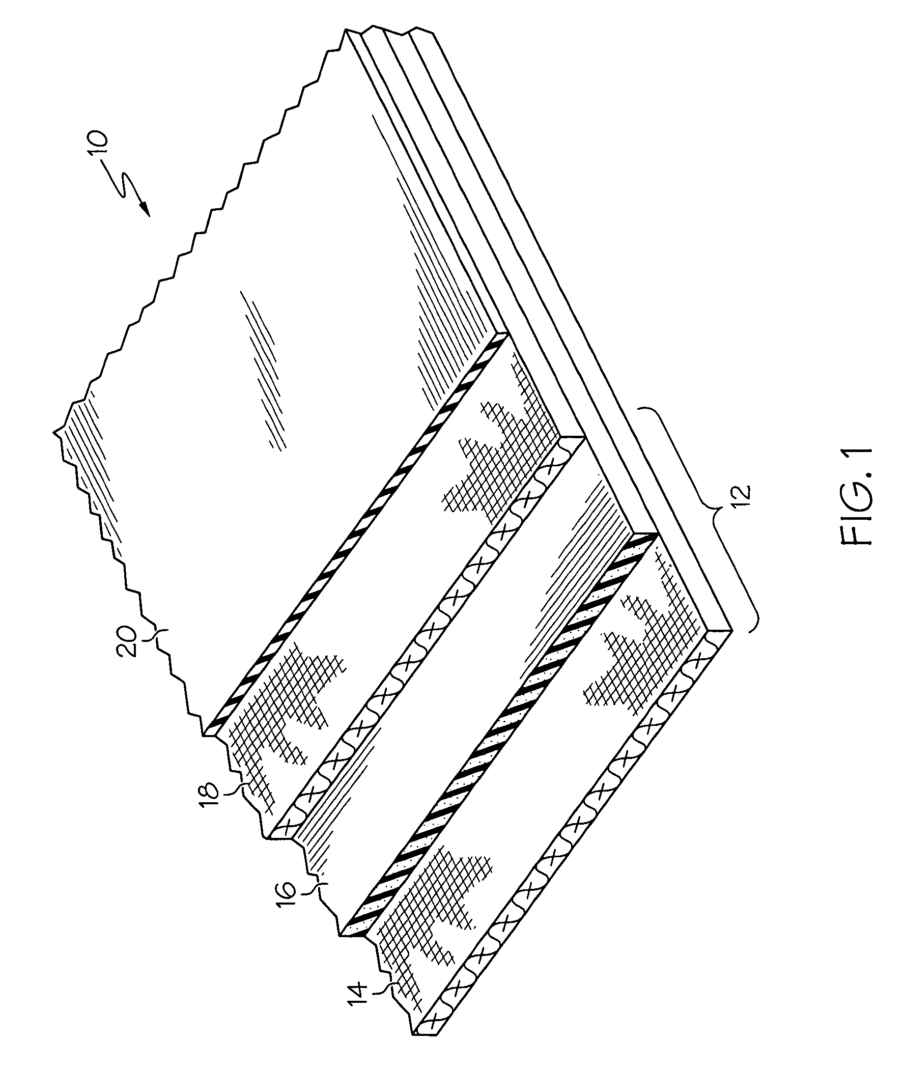
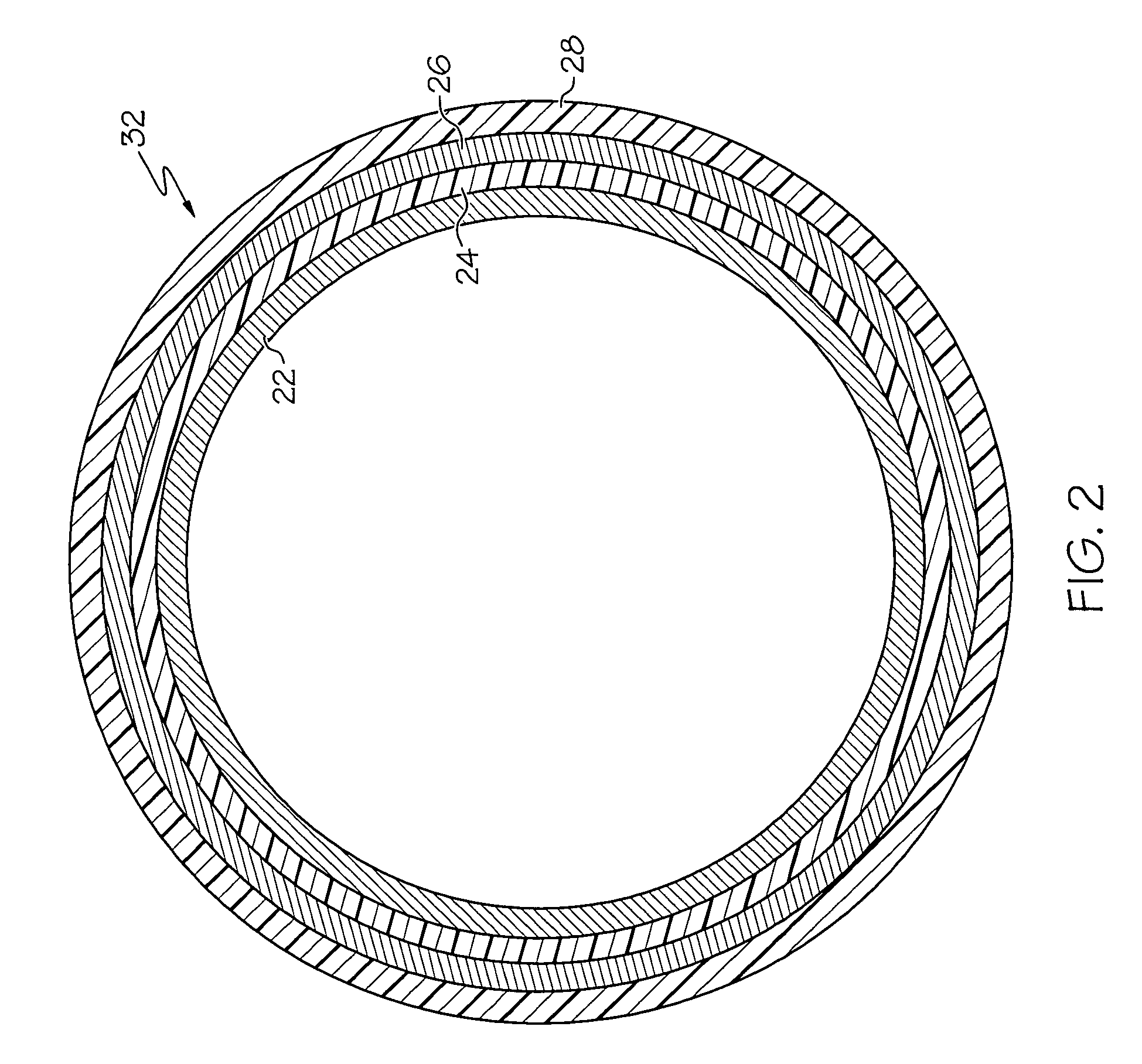
[0021]We have found that the use of an image reinforcement layer having a smooth surface allows the use of a very thin printing face layer in a blanket or sleeve construction. The smooth image reinforcement layer provides sufficient gauge and surface uniformity so that a much thinner print face can be applied without the problem of threads, patterns, or textures showing through from the underlying reinforcement layer to the printing face or to the printed image. The printing surface layer of the present invention has a thickness of from about 0.001 to 0.012 inches (about 0.025 to about 0.3 mm), while prior art printing surface layer thicknesses are typically from about 0.012 to 0.020 inches (0.3 mm to 0.51 mm) in thickness.

[0022]And, because a much thinner printing surface layer requires less rubber material, the amount of solvent needed for the surface layer is reduced. In addition, where the image reinforcement layer is formed from a 100% solids material such as thermoplastic poly...


PUM

PropertyMeasurementUnit
thicknessaaaaaaaaaa
thicknessaaaaaaaaaa
thicknessaaaaaaaaaa

Abstract

An image transfer product such as an offset printing blanket or sleeve is provided which comprises a very thin printing surface layer in combination with a smooth image reinforcement layer comprising a polymeric film, a fabric, or a polymer-coated fabric. The thin printing surface layer has a thickness between about 0.001 to about 0.012 inches (about 0.025 to about 0.3 mm). The image transfer product is more efficiently manufactured due to reduced solvent usage and reduced number of coating passes, and in use, exhibits uniform feed, web control, and registration characteristics.

Description

CROSS-REFERENCE TO RELATED APPLICATIONS[0001]This application claims the benefit of U.S. Provisional Application No. 60 / 991,226, filed Nov. 30, 2007, entitled IMAGE TRANSFER PRODUCT INCLUDING A THIN PRINTING SURFACE LAYER. The entire contents of said application are hereby incorporated by reference.BACKGROUND OF THE INVENTION[0002]The present invention relates to an image transfer product such as a printing blanket or printing sleeve, and more particularly, to an improved image transfer product including a thin printing surface layer in combination with a smooth image reinforcement layer.[0003]One of the most common commercial printing processes is offset lithography. In this printing process, ink is offset from a printing plate to a rubber-surfaced printing blanket mounted on a blanket cylinder before being transferred to a substrate, such as paper. Typically, the printing blanket includes at least one base ply which comprises the blanket carcass and an outer printing surface layer...

Claims


Application Information

Patent Timeline
Patent Type & Authority Patents(United States)
IPC IPC(8): B32B27/32B32B27/00B32B27/40B32B5/16B32B25/04B29C47/00B41N1/00B32B5/26B32B27/12
CPCB41N10/04B41N2210/04Y10T156/10Y10T428/26Y10T428/264B41N2210/14Y10T428/31569Y10T442/659Y10T428/31551Y10T428/31826Y10T442/674
Inventor BYERS, JOSEPH L.FLINT, W. TORIRANSHUMAN, SAMUEL R.
Owner DAY INT
Why Eureka
Try Eureka