Medical laser target marker and its use

a laser target and laser technology, applied in the field of calibration testing of medical tracking systems, can solve the problem that markers cannot be calibrated in situ

Inactive Publication Date: 2013-04-02
BRAINLAB
View PDF10 Cites 34 Cited by
  • Summary
  • Abstract
  • Description
  • Claims
  • Application Information

AI Technical Summary

Problems solved by technology

One problem with calibrating such tracking systems, however, is that the markers often cannot be calibrated in situ, i.e., at the site of installation in the hospital or in the operating theaters.

Method used


Image

  • Medical laser target marker and its use
  • Medical laser target marker and its use

Examples


Embodiment Construction

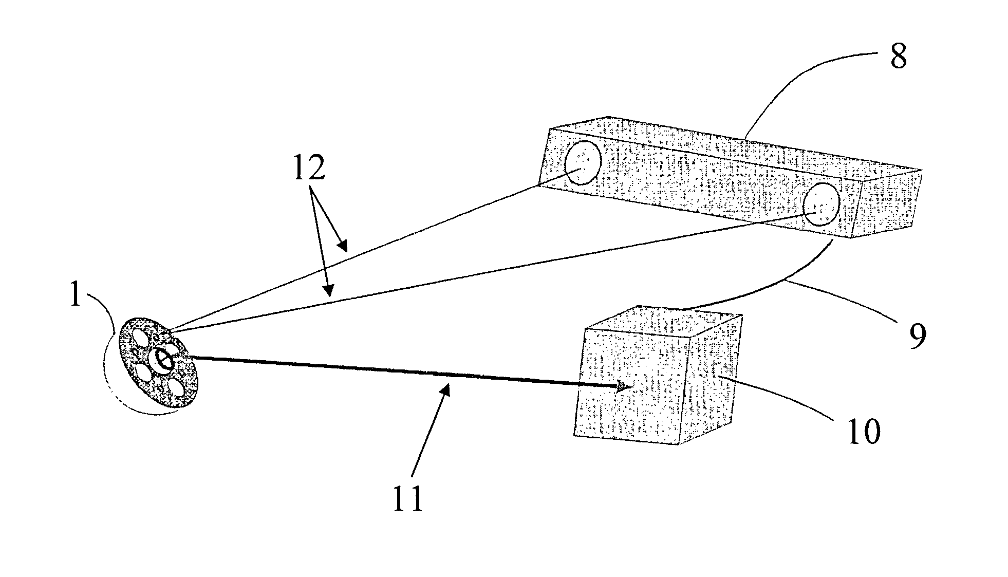
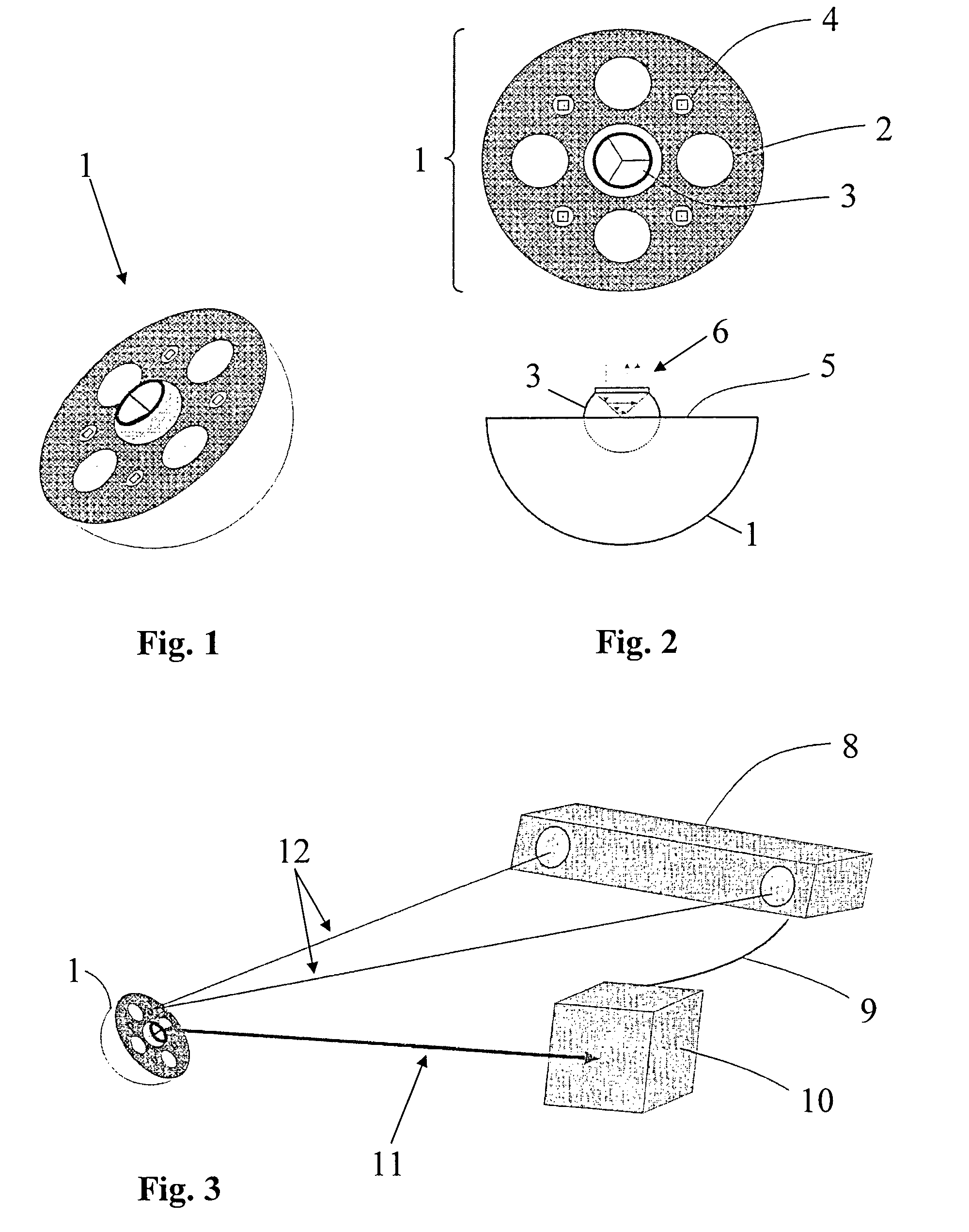
[0023]An exemplary multi-marker laser target marker in accordance with an embodiment of the present invention is described with reference to FIGS. 1 and 2. The exemplary marker as a whole bears the reference sign 1 and has a substantially hemispherical shape. In the middle of its circular sectional plane 5, the marker 1 bears a so-called SMR target 3. The SMR target 3 comprises a cut sphere that protrudes out from the plane 5 and includes three reflection surfaces that are relieved towards a center portion, wherein the reflection surfaces are perpendicular to each other. Due to this arrangement of the reflection surfaces, incident light or laser beams are always reflected parallel to their direction of incidence, as shown by the reference sign 6. The reflected light returns along the same path in each case, namely always the path corresponding to a reflection at the center point of the sphere of the SMR target. Using this SMR target, it is possible to perform high-accuracy laser dis...


PUM


Abstract

A medical laser target marker includes a retro-reflector for receiving and reflecting light, at least one first medical tracking marker, and at least one second medical tracking marker. The at least one first medical tracking marker is arranged on the laser target marker and has a first functional configuration. The at least one second medical tracking marker is arranged on the laser target marker and has a second functional configuration different from the first functional configuration.

Description

RELATED APPLICATIONS DATA[0001]This application claims priority of U.S. Provisional Application No. 60 / 893,282 filed on Mar. 6, 2007, which is incorporated herein by reference in its entirety.FIELD OF THE INVENTION[0002]The invention relates to calibration and / or calibration testing for medical tracking systems and, more particularly, to a medical laser target marker and its use.BACKGROUND OF THE INVENTION[0003]Medical tracking systems can be used to ascertain a spatial position of tracking markers. When such markers are attached to objects, such as medical instruments and / or on patients, then the spatial position of the objects and / or patients also can be ascertained and provided to a medical navigation system, which enables image-guided surgery. Since the accuracy of such tracking systems is highly important for correct navigation, the systems are calibrated.[0004]Calibrated systems provide precise positional data of the detected tracking markers. One problem with calibrating such...

Claims


Application Information

Patent Timeline
Patent Type & Authority Patents(United States)
IPC IPC(8): A61B5/05
CPCA61B19/54G02B5/12A61B2017/00725A61B2019/5437A61B2019/5445A61B2019/5458A61B2019/5483A61B90/39A61B2090/3937A61B2090/3945A61B2090/3958A61B2090/3983
Inventor GOLDBACH, GUNTER
Owner BRAINLAB
Why Eureka
Try Eureka