Calibrating aircraft surfaces

a technology for aircraft surfaces and aircraft, applied in the field of aircraft surfaces, can solve the problems of reducing the operational efficiency of aircraft, reducing the scale of aircraft, and merely representing illustrations, so as to reduce the drag of aircra

Active Publication Date: 2010-08-12
THE BOEING CO
View PDF7 Cites 27 Cited by
  • Summary
  • Abstract
  • Description
  • Claims
  • Application Information

AI Technical Summary

Benefits of technology

[0005]In another particular embodiment, a method includes determining a first as-built position of a first wing of an aircraft and determining a second as-built position of a second wing of the aircraft. The method also includes generating an aerodynamic representation of the aircraft using the first as-built position and the second as-built position. The method further includes determining an installation location of an aircraft component to reduce drag of the aircraft based on the aerodynamic representation.

Problems solved by technology

For example, when aircraft are being assembled, improper placement of a functional group may reduce operational efficiency of the aircraft.
Additionally, the illustrations are merely representational and may not be drawn to scale.

Method used


Image

  • Calibrating aircraft surfaces
  • Calibrating aircraft surfaces
  • Calibrating aircraft surfaces

Examples


first embodiment

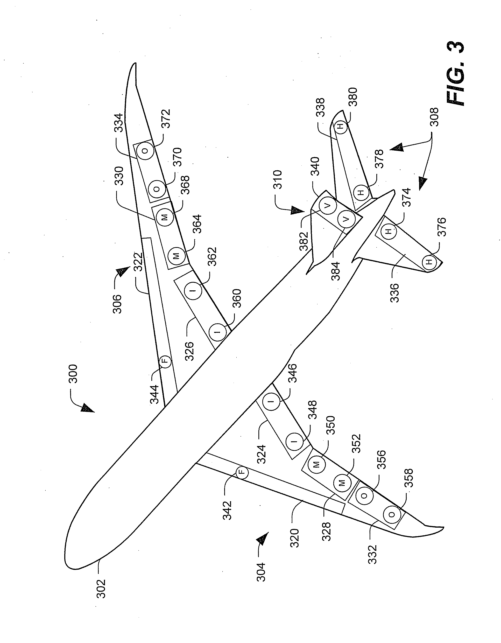
[0024]FIG. 3 is an illustration of an aircraft 300 and an aircraft surface calibration system. The aircraft 300 includes a fuselage 302, a first wing 304, a second wing 306, and a plurality of tail surfaces, such as horizontal stabilizers 308 and a vertical stabilizer 310. The wings 304, 306 and the tail surfaces 308, 310 include a plurality of control surfaces. For example, the wings 304, 306 may include Krueger flaps 320, 322 on a leading edge of the wings 304, 306. In another example, the wings 304, 306 may include inboard flaps 324, 326; mid-line flaps 328, 330; outboard ailerons 332, 334; other control surfaces; or any combination thereof. The tail surfaces 308, 310 may include control surfaces, such as a rudder 340 coupled to the vertical stabilizer 310; elevators 336, 338 coupled to the horizontal stabilizers 308; other control surfaces; or any combination thereof.

[0025]In a particular embodiment, during or after assembly of the aircraft 300, calibration devices are coupled t...

second embodiment

[0028]FIG. 4 shows a first illustration of the aircraft 300 and an aircraft surface calibration system. The aircraft surface calibration system includes a plurality of calibration devices 442-484. Each of the calibration devices 442-484 may be coupled to a surface of the aircraft 300. For example, the calibration devices 442-484 may be coupled to the wings 304, 306; the tails surfaces 308, 310, other aircraft surfaces, or any combination thereof. In a particular embodiment, the calibration devices 442-484 are coupled to control surfaces (not shown in FIG. 4) such as flaps, ailerons, elevators, rudders, and so forth.

[0029]In a particular embodiment, each of the calibration devices 442-484 includes a set of laser targets. For example, a first exemplary calibration device 458 includes at least a first laser target 402 and a second laser target 404. The first laser target 402 may be adapted to be coupled to a first side of a surface of the aircraft 300 and the second laser target 404 ma...


PUM

PropertyMeasurementUnit
aerodynamic modelingaaaaaaaaaa
incline angleaaaaaaaaaa
aerodynamic representationaaaaaaaaaa

Abstract

Systems and methods to calibrate aircraft surfaces are provided. A particular method includes installing a set of laser targets. The set of laser targets includes at least first laser target and a second laser target. The first laser target is installed on a first side of a first aircraft surface and the second laser target is installed on a second side of the first aircraft surface at a known location relative to the first laser target. The method also includes determining a first position of the first laser target with a first laser device. The method further includes determining a second position of the second laser target with a second laser device. The method includes determining a position of the first aircraft surface based on the first position of the first laser target and the second position of the second laser target.

Description

FIELD OF THE DISCLOSURE[0001]The present disclosure is generally related to calibrating aircraft surfaces.BACKGROUND[0002]Certain aircraft and other large machines use modular assembly techniques. For example, the aircraft or machine may be assembled using relatively large functional groups. To illustrate, rather than assembling an entire aircraft from the ground up as a single unit, the assembly process may be broken up so that functional modules are assembled separately and later joined together. For example, wings may be assembled from many pieces at a first assembly location then attached as a single unit to a fuselage assembly at a second location. Placement of these modules or functional groups can be an important aspect of the assembly process. For example, when aircraft are being assembled, improper placement of a functional group may reduce operational efficiency of the aircraft.SUMMARY[0003]Systems and methods to calibrate aircraft surfaces are disclosed. A particular meth...

Claims


Application Information

Patent Timeline
Patent Type & Authority Applications(United States)
IPC IPC(8): G01B11/26G01B11/27G06G7/48B23P11/00
CPCB64F5/00Y10T29/4978G01B11/272G01B11/002
Inventor MARSH, BOBBY J.LAZAR, MICHAEL A.
Owner THE BOEING CO
Why Eureka
Try Eureka