Detection device for laser rangefinder

A laser range finder and detection device technology, applied in the direction of radio wave measurement systems, instruments, etc., can solve the problems of easy damage to the target surface, difficulty in aligning and debugging the optical axis of the receiving system, and invisibility

Inactive Publication Date: 2011-11-16
南瑶
View PDF5 Cites 29 Cited by
  • Summary
  • Abstract
  • Description
  • Claims
  • Application Information

AI Technical Summary

Problems solved by technology

The photoelectric simulation method mainly uses fast photodetectors, delay circuits, analog light sources and standard attenuators. The emitted laser energy of the laser rangefinder is not directly related to the received laser energy, and the optical axis of the simulated light source and the receiving system of the laser rangefinder is aligned. Quasi-debugging is difficult
The optical fiber simulation method usually uses a certain length of optical fiber to make a standard distance simulator, samples and delays the laser pulse, and inputs the laser pulse output from the optical fiber into the receiving system of the laser rangefinder for a single distance simulation, and one optical fiber can only simulate One distance; the calibration methods of the simulated distance and laser energy attenuation loss of the standard distanc

Method used


Image

  • Detection device for laser rangefinder
  • Detection device for laser rangefinder
  • Detection device for laser rangefinder

Examples


Embodiment 1

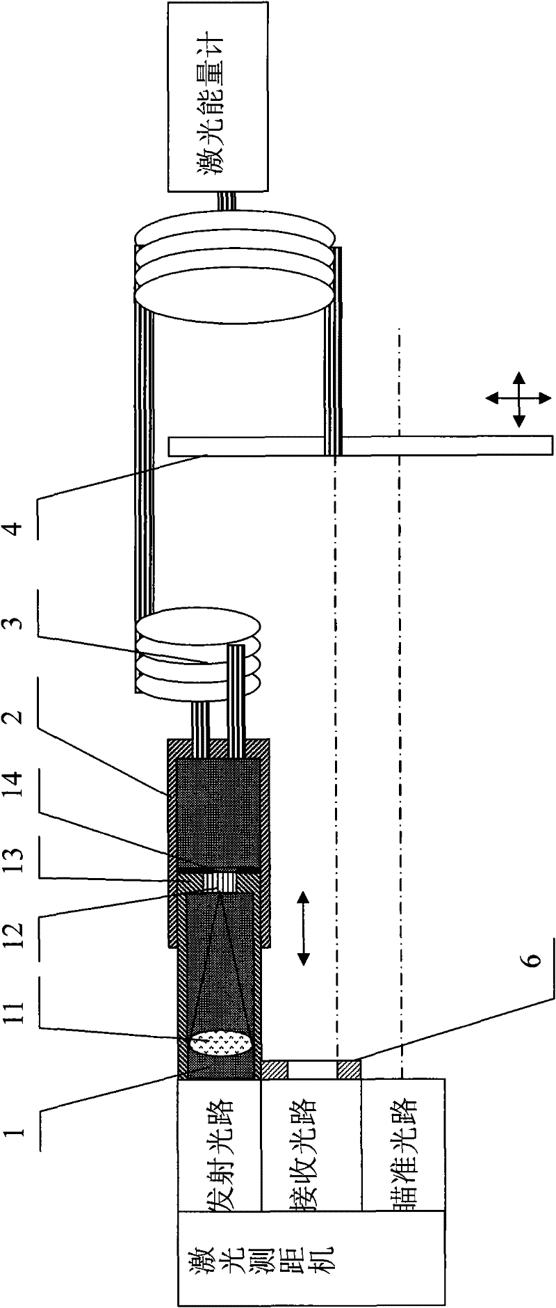
[0035] according to figure 1 , The preferred embodiment 1 of the present invention detects a laser distance measuring machine with a laser wavelength of 1.064 μm, including a sampler 1 , an absorber 2 , a multi-target simulator 3 , a standard target plate 4 , and an iris 6 . The sampler 1 includes a standard lens 11, a beam expander 12, a mirror tube 13, and a small target aperture 14. The preferred standard lens 11 is an aberration-absorbing lens made of quartz with a focal length of 300 mm and an aperture of 30 mm converging laser light. The effective optical diameter of the emitting light path is 30mm; the preferred beam expander 12 is made of quartz optical fiber, a bare optical fiber rod with a length of 5mm, which is cut by a special cutter, and the outer diameter of the optical fiber rod is coated with a metal reflective film to form a tight bundle; preferably small There is a 0.4mm through hole in the middle of the target aperture 14, the laser spot at the focal plane ...

Embodiment 2

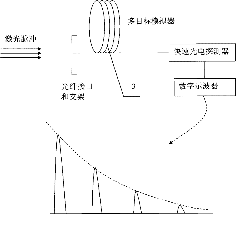
[0040] according to figure 1 , The preferred embodiment 2 detects a laser distance measuring machine with a laser wavelength of 10.6 μm, including a sampler 1 , an absorber 2 , a multi-target simulator 3 , a standard target plate 4 , and an iris 6 . The standard lens 11 of the preferred sampler 1 is a germanium lens that transmits far-infrared light. The preferred beam expander 12 adopts As-Se optical fiber material and a bare optical fiber rod with a length of 5 mm, which is cut by a special cutter. Metal-plated reflective film, tightly bundled; the preferred small target aperture 14 is made of ceramic materials; the preferred multi-target simulator 3 is composed of 2x5 As-S optical fibers with different lengths, and the lengths are 51m, 53m, 57m, 59m, 61m two each, preferably the input / output end face of the As-S fiber is flat and perpendicular to the optical axis of the fiber, coated with the same reflective film for the laser wavelength of 10.6μm; the simulated distance of...

Embodiment 3

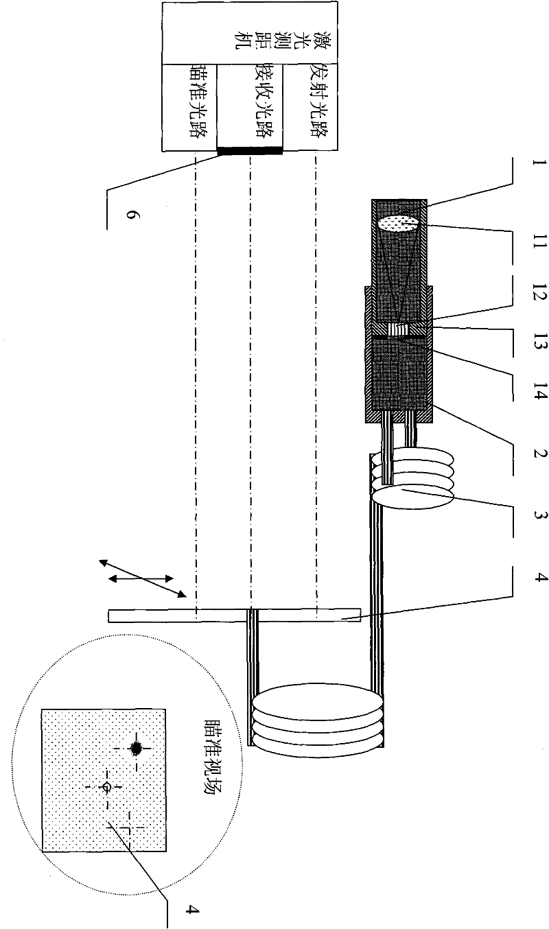
[0042] according to Figure 4 , the preferred embodiment 3 carries out long-distance detection to the laser range finder, including multi-target simulator 3, standard target plate 4, self-focusing lens 5 and interface, the distance between laser range finder and standard target plate 4 is 60m, and the standard target Board 4 is vertical to the optical axis of the laser, the optical axis of the self-focusing lens is coaxial with the optical axis of the laser, the laser is launched for distance measurement, the gate distance of the laser range finder is adjusted, and the performance of the laser range finder is evaluated according to the ranging results.


PUM


Abstract

The invention discloses a detection device for a laser rangefinder, composed of a sampler, an absorber, a multi-target simulator, a standard target and a variable diaphragm. The laser rangefinder emits a laser directed at the detection device; the sampler and the multi-target simulator simulate a laser target echo, and obtain an receiving optical axis and the minimum detectable power of the laser rangefinder via the maximum distance ranging result; a laser emitting optical axis and a collimation optical axis are corrected via a laser spot position and an axis distance; and the emission and the receiving of the laser rangefinder are quantitatively associated, in order to realize a ranging capacity evaluation of the laser rangefinder. The device disclosed by the invention has no need to be supplied with power, and is simple in operation and low in cost.

Description

technical field [0001] The detection field of the laser range finder of the present invention mainly relates to a measuring device for detecting and calibrating the laser range finder at the site where the laser range finder is used. Calibrated measuring methods and measuring devices. Background technique [0002] Whether the performance and technical indicators of the laser rangefinder are normal or not is the most concerned by users. The maximum range, minimum range, distance accuracy, and extinction ratio of the laser rangefinder for different targets under certain environmental conditions are the main technical indicators for the evaluation of the rangefinder capability. Other technical indicators that affect the performance of the laser range finder include the beam divergence angle of the emitted laser, the laser spot mode, the jitter of the laser optical axis, the peak power of the laser, the minimum detectable power of the laser receiving system, the laser emitting ...

Claims


Application Information

Patent Timeline
IPC IPC(8): G01S7/497
Inventor 不公告发明人
Owner 南瑶
Why Eureka
Try Eureka