Non-cooperative laser target enhancement system and method

a laser target enhancement and non-cooperative technology, applied in the direction of optical elements, instruments, optical radiation measurement, etc., can solve the problems of reducing the performance of imaging or laser projection systems, many fundamental challenges, and the method has an important limitation that has remained unsolved

Active Publication Date: 2011-12-13
NLIGHT DEFENSE SYST INC
View PDF16 Cites 25 Cited by
  • Summary
  • Abstract
  • Description
  • Claims
  • Application Information

AI Technical Summary

Benefits of technology

[0012]Yet another aspect of the present invention is to allow for the formation of a narrow size region of coherent laser light at a target.

Problems solved by technology

Adaptive optical system technology can potentially enhance any application in which turbulence along the path, which leads to refractive index fluctuations due to temperature variations, degrades the performance of an imaging or laser projection system.
These methods have an important limitation that has remained unsolved throughout the history of the field: the only highly successful applications of adaptive optical systems to date are when a “cooperative” point source laser beacon at the target is provided.
Many fundamental challenges exist in the case of a non-cooperative target.
There is no prior art directly addressing the problem of adaptive optical systems with a non-cooperative target.
There is significant prior art associated with the problem of both weak and challenging turbulence scenarios with a cooperative point source beacon.
It is also known that in such scenarios the performance of conventional target return and laser guide star return based adaptive optical systems suffer significant performance degradations.

Method used


Image

  • Non-cooperative laser target enhancement system and method
  • Non-cooperative laser target enhancement system and method
  • Non-cooperative laser target enhancement system and method

Examples


Embodiment Construction

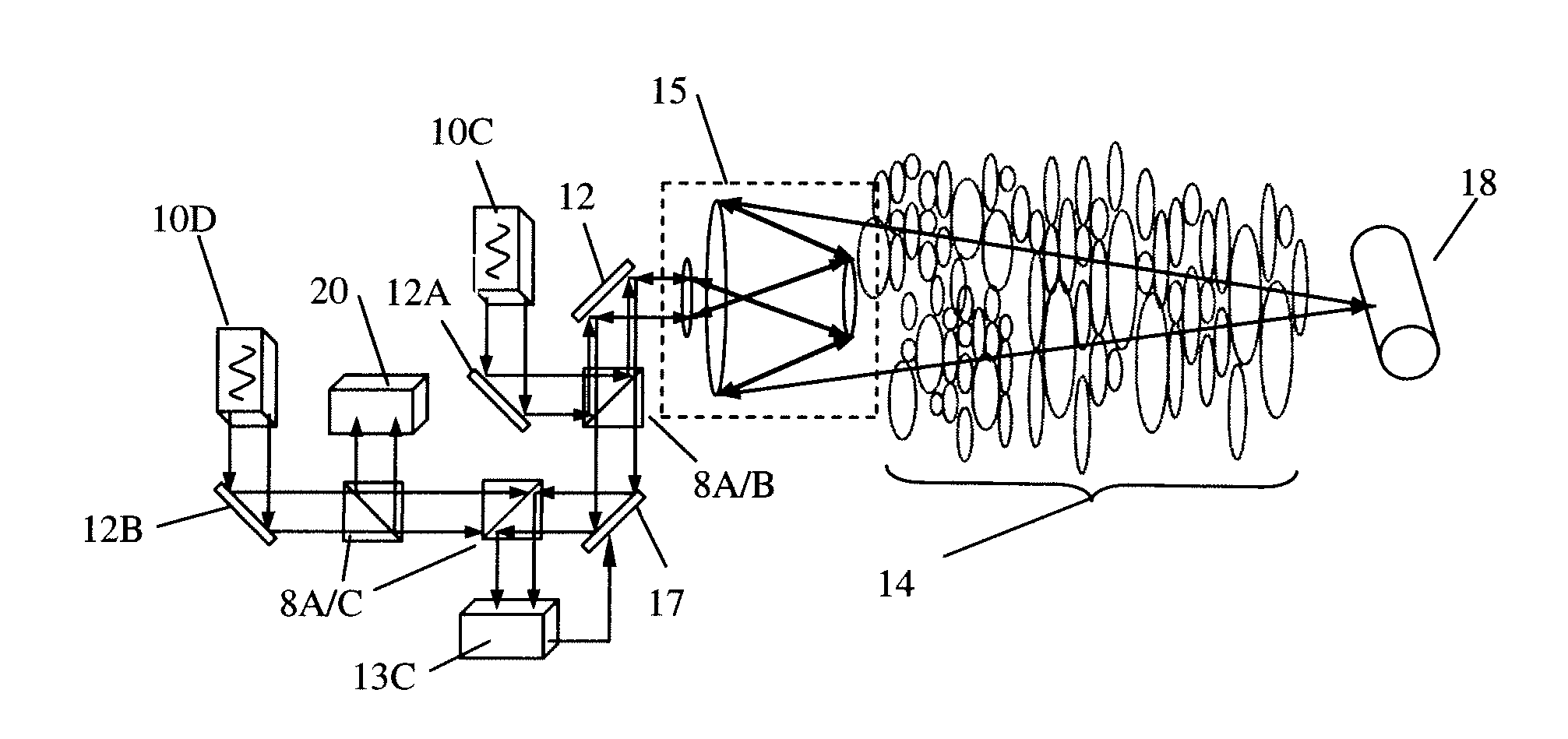
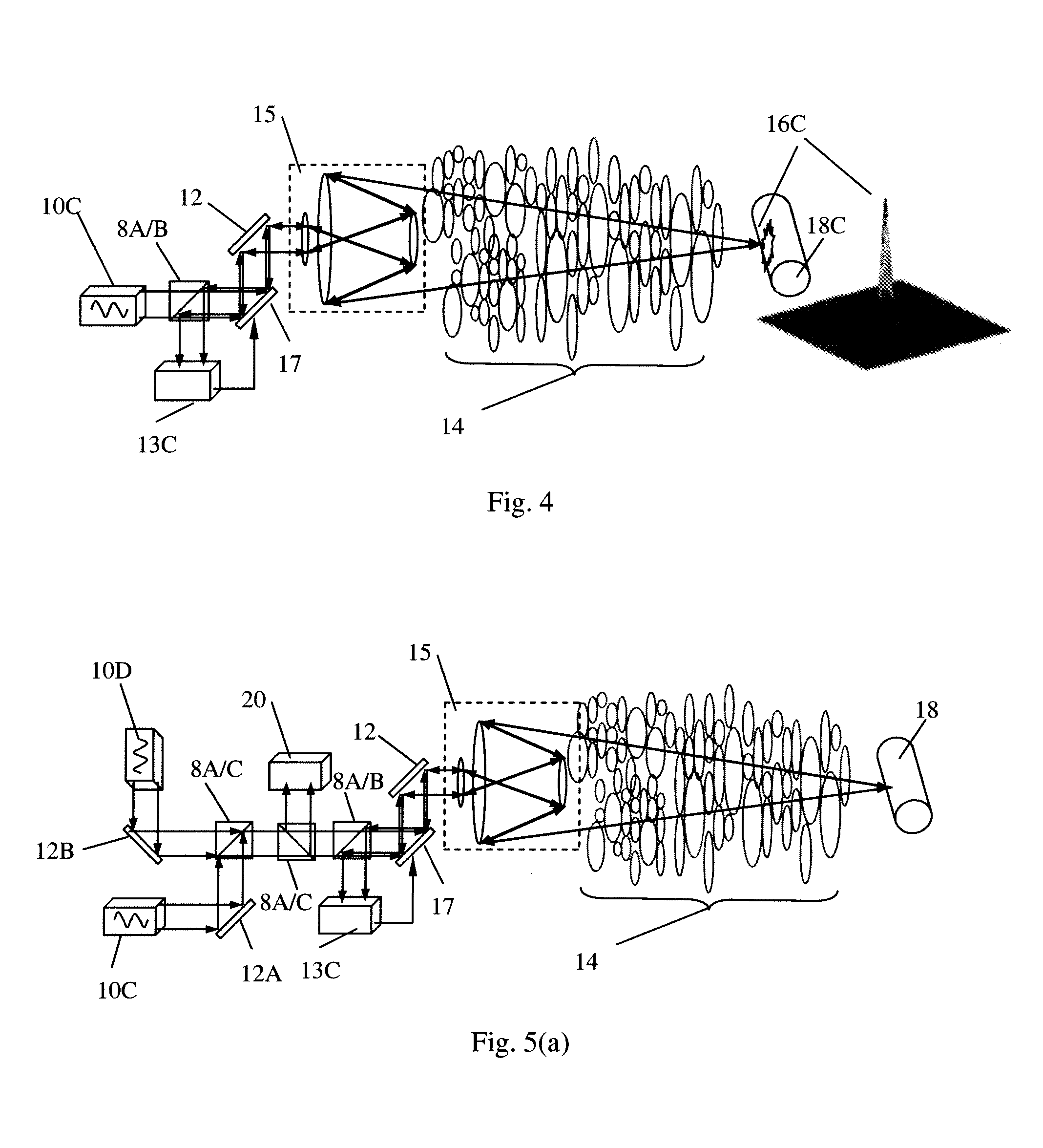
[0035]The present invention describes a method, denoted Broadband Coherent Adaptive Optics (BCAO), and preferred embodiment to implement the method for forming a near diffraction limited size beacon at a non-cooperative target. The critical elements of the BCAO system are shown in FIGS. 5a, 5b and 6.

[0036]The BCAO system of the present invention comprises:[0037](1) A partially coherent laser—defined as a carrier envelope phase stabilized laser with a temporal coherence length, lc=λ2 / Δλ, less than 10Neλ5, where Ne is the effective number of control channels across the aperture [Ne=(Ntotπ)1 / 2, where Ntot is the total number of controlled modes or control channels], λ is the center wavelength, and Δλ is the spectral bandwidth of the laser source—that is either pre-compensated (ref. FIGS. 5a, 5b—where FIG. 5a indicates additional pre-compensation of one or more scoring laser beams to the target and FIG. 5b indicates compensation only for imaging) or not pre-compensated (FIGS. 6a, 6b—whe...


PUM


Abstract

A system and method forming near diffraction limited size beacon for adaptive optical system using a temporally partially coherent laser source. Comprises projection of laser beams through turbulent medium having non-cooperative target using combination of adaptive optical system and short temporal coherence length laser source forming controllable focused laser target beacon. Combines adaptive optical system technology using any wavefront sensing technique making complex field measurements with short coherence length and associated broad spectral bandwidth. The partially coherent laser source forms narrow (near diffraction limited) size region of coherent laser light at target. The coherent region of return dominates signal for any measurement technique computing average of field over wavelength bandpass and can be used to pre-compensate either the partially coherent laser beam, a long coherence length beam of different wavelength or wavelength in bandpass, or both. Pre-compensation of the partially coherent laser beam can lead to signal-to-noise ratio enhancements.

Description

CROSS REFERENCE APPLICATIONS[0001]This application is a non-provisional application claiming the benefits of provisional application No. 60 / 973,622 filed Sep. 19, 2007.FIELD OF INVENTION[0002]The present invention relates to a method and several system implementations for projection of laser beams through a turbulent medium with a non-cooperative target using a combination of an adaptive optical system and an ultra-short temporal coherence length laser source to form a controllable focused laser beacon at the target. A non-cooperative target refers to a target in which no laser beacon is provided directly by the target for wavefront sensing. The present invention provides a system and method to form a near diffraction limited size beacon for an adaptive optical system using a temporally partially coherent laser source.BACKGROUND OF THE INVENTION[0003]Adaptive optical system technology has proven itself invaluable to a number of applications such as astronomical imaging and long rang...

Claims


Application Information

Patent Timeline
Patent Type & Authority Patents(United States)
IPC IPC(8): G01J1/20
CPCF41H13/005G02B26/06G01J1/20
Inventor BARCHERS, JEFFREY D.
Owner NLIGHT DEFENSE SYST INC
Why Eureka
Try Eureka