
Visual interface element transition effect

a transition effect and visual interface technology, applied in the field of graphical user interfaces, can solve the problems of user distraction from the meeting, bored audience members drifting away, abrupt changes may be jarring, etc., and achieve the effect of preventing abrupt or startling transitions

Active Publication Date: 2013-04-02
ADOBE INC
View PDF9 Cites 3 Cited by
  • Summary
  • Abstract
  • Description
  • Claims
  • Application Information

AI Technical Summary

Benefits of technology

This approach maintains user context and attention by providing a seamless transition experience, enhancing the presenter's presence and audience engagement by making changes appear deliberate and purposeful, reducing the likelihood of misinterpreting screen changes as glitches.

Problems solved by technology

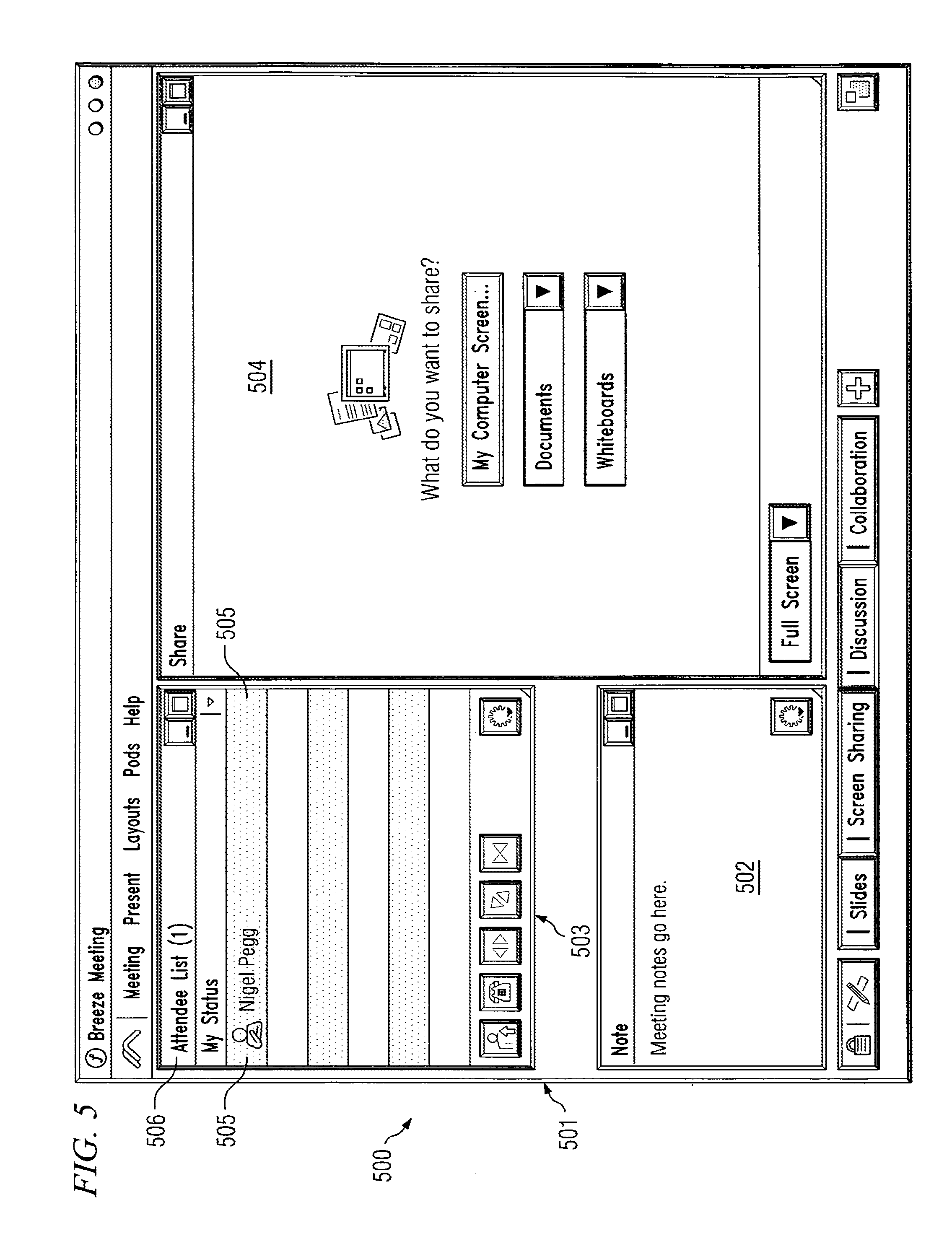
For a host, such screen changes may not be distracting, but to an audience of meeting participants or users, the lack of context to the change may leave them wondering about whether the screen change was purposeful or was a network glitch, or maybe even wondering what the nature of the change was, such as exactly which pods or elements were just removed or added.
Further, such abrupt changes may be jarring, especially to passive audience members who may be focusing on the screen.
Any kind of interruption to the host presenter's message may also cause bored audience members to drift away instead of paying attention to the meeting.
Also, a user who is paying attention may be distracted from the meeting by an abrupt change.
In the past, some hosts have adapted by announcing screen changes, such as by saying, “and now I am changing the screen.” However, such announcements may cause a host to pause and lose his, or the audience's, attention.
Moreover, the presenter may forget to warn the participants of the impending change.

Method used


Image

  • Visual interface element transition effect
  • Visual interface element transition effect
  • Visual interface element transition effect

Examples


Embodiment Construction

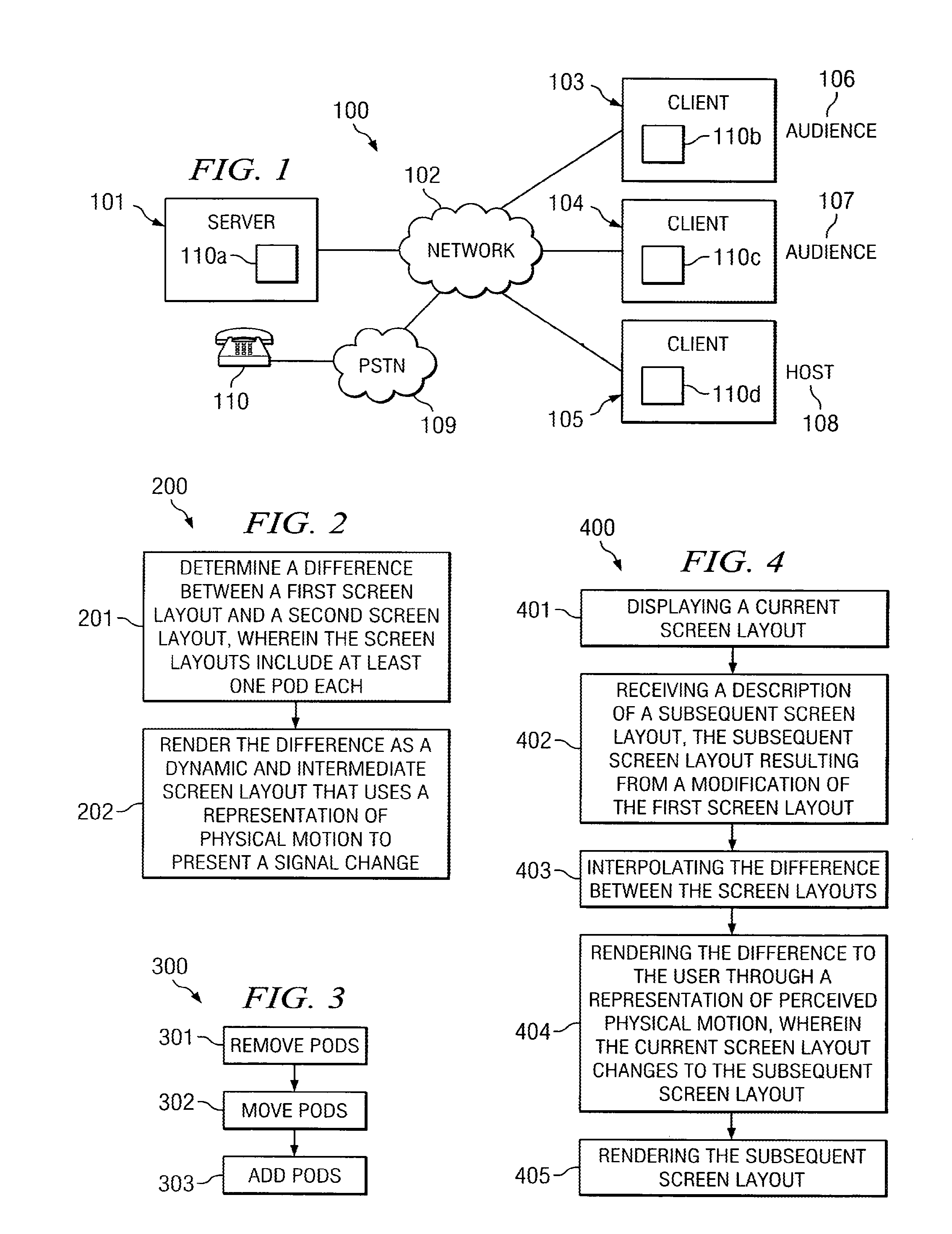
[0019]FIG. 1 illustrates exemplary system 100, according to one embodiment of the present invention. System 100 includes server computer 101 separated from client computers 103-105 by network 102. Network 102 may be a Local Area Network (LAN), Wide Area Network (WAN), the Internet, or the like. Client computers 103-105 are associated with users 106-108. Users 106 and 107 may each be one or more intended audience members for a presentation conducted using system 100. Host user 108 may be one or more intended presenters or moderators for the presentation.

[0020]Each of computers 101 and 103-105 execute computer application 110, which is adapted to allow computers 101 and 103-105 to perform functions according to the present invention. In this particular embodiment, computer application 110 is a web-based personal interaction meeting space, such as BREEZE®, available from Macromedia, Inc., of San Francisco, Calif., and server application 110a is different than client applications 110b-d...


PUM


Abstract

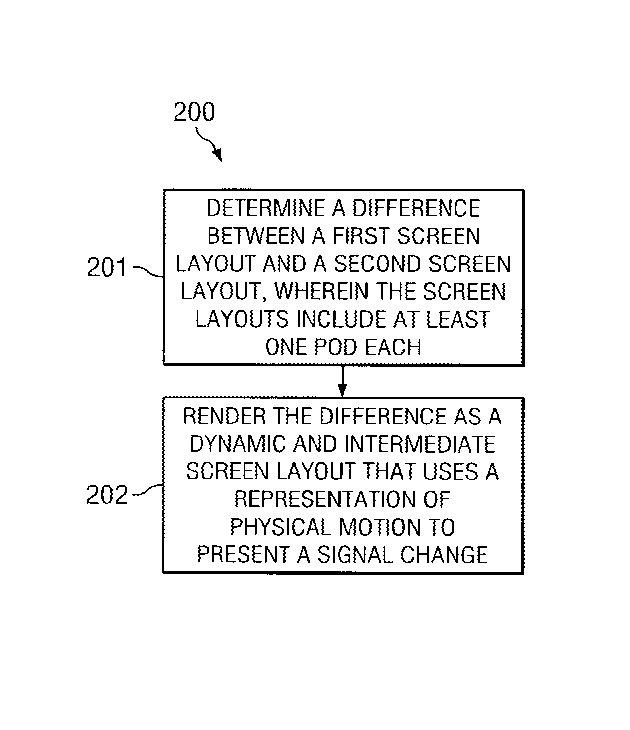
In an electronic interaction space, transitioning between a first and second screen layout includes determining a difference between the first and second screen layouts, wherein the first and second screen layouts include at least one pod each, and rendering the difference as a dynamic and intermediate screen layout that uses a representation of physical motion to present a gradual change.

Description

PRIORITY CLAIM[0001]This application claims priority as a continuation of U.S. patent application Ser. No. 11 / 103,344, filed Apr. 11, 2005, which is incorporated by reference herein in its entirety.TECHNICAL FIELD[0002]The present invention relates, in general, to graphical user interfaces, and, more specifically, to transitions between multiple interface layouts.BACKGROUND OF THE INVENTION[0003]Currently, the standard way that users interact with computers is through Graphical User Interfaces (GUIs). GUIs are usually associated with moveable windows, elements or pods, and a mouse (or other pointing device) and offer users a more intuitive interaction with computers than character-based interface alternatives. An example of a GUI is the popular WINDOWS® operating system, available from Microsoft Corporation. Applications that use GUIs are numerous, and include word processing applications, spreadsheets, databases, and the like.[0004]One specific example of a type of application that...

Claims


Application Information

Patent Timeline
Patent Type & Authority Patents(United States)
IPC IPC(8): G06F3/048G06F3/00
CPCG06F9/4443G06F9/451
Inventor PEGG, NIGEL
Owner ADOBE INC
Learn More