Head rest apparatus

a head rest and apparatus technology, applied in the field of head rest apparatuses, can solve the problems of abnormal noise generation, loose connection between the front and rear covers, and gap between resin and metal, and achieve the effect of preventing abnormal noise generation and preventing any rattling

Inactive Publication Date: 2013-04-09
TOKAI CHEM IND CO LTD
View PDF15 Cites 15 Cited by
  • Summary
  • Abstract
  • Description
  • Claims
  • Application Information

AI Technical Summary

Benefits of technology

[0014]According to the head rest apparatus of the invention, the flat plate portion of the metal plate is tightly fixed to the first divided body by means of a fixing means integrally formed with the first divided body. Accordingly, even when the vibration is transmitted from the seat back to the metal plate or metal stay, the stress applied from the flat plate portion is transmitted only to the first divided body and no loosening of the connecting surface between the first and the second divided bodies. Further, when the head rest position is adjusted in a front / rear direction by swinging the head rest main body, the stress applied from the flat plate portion is transmitted only to the first divided body and the stress is absorbed within the first divided body, not to loosen the connection strength between the first and the second divided bodies. Thus, without using any damping material, the generation of rattling in operation or abnormal noise can be surely prevented.
[0015]It is preferable for a fixing means to provide a contact surface to be in contact with the front side surface of the flat plate portion. Since the fixing means includes a contact surface, the loosening of the flat plate portion from the first divided body can be surely prevented and thereby to prevent generation of rattling in operation.
[0016]It is preferable to provide a support portion to be in contact with at least a portion of the rear side surface of the flat plate portion at the first divided body and it is also preferable to hold the flat plate portion by sandwiching the flat plate portion between the contact surface and the support portion. By thus structuring, the flat plate portion is further tightly fixed to the first divided body to surely prevent rattling in operation.
[0017]It is preferable to provide a guide portion such as a tapered surface on the fixing means for guiding the flat plate portion along the contact surface. By providing the guide portion, the assembling workability of the first divided body to the metal plate is improved.
[0018]It is preferable to form the support portion at least on two portions of the first divided body and form the fixing means between the two support portions. Thus, the flat plate portion can be fixed at least with three points to further assure the fixing strength.
[0019]It is preferable to provide the flat plate portion having an approximately rectangular shape and the fixing means having a pair of holding pawls including a pair of root portions respectively facing a corresponding pair of edge surfaces of the flat plate portion extending in parallel to each other and a pair of head portions projecting from the pair of root portions facing each other and covering a portion of the front side surface of the flat plate portion thereby the lower surface of the head portions forming the contact surface and the head portions of the pair of holding pawls and the support portions sandwiching the flat plate portion. Since the flat plate portion is sandwiched by the head portions of the pair of holding pawls and the support portions, the metal plate can be tightly fixed to the first divided body. Further, when the head rest main body is rotated to adjust the front / rear position thereof, the stress is only applied on the first divided body and the first divided body is tightly held by the holding pawls to absorb the stress by the first divided body alone. The connection between the first and the second divided bodies would not be loosened thereby to prevent rattling operation or generation of abnormal noise.

Problems solved by technology

However, the resin to resin connection may generate a gap between the resin cover and the metal plate or the resin cover and the metal stay due to the contraction after molding or depending on the accuracy in shape of metal plate.
Further, since the metal plate and the metal stay are fixed by sandwiching thereof with the front and rear resin covers, the connection between the front and rear covers may loosen due to the vibration from the seat back and the gap between the resin and metal may be also generated.
When such gap is generated, resin cover and the metal plate or resin cover and the metal stay hit or bump each other due to the vibration generated under the vehicle being running and such hitting generates an abnormal noise.
The method however, needs more number of parts and assembling man-hours.

Method used


Image

  • Head rest apparatus
  • Head rest apparatus
  • Head rest apparatus

Examples


embodiment 1

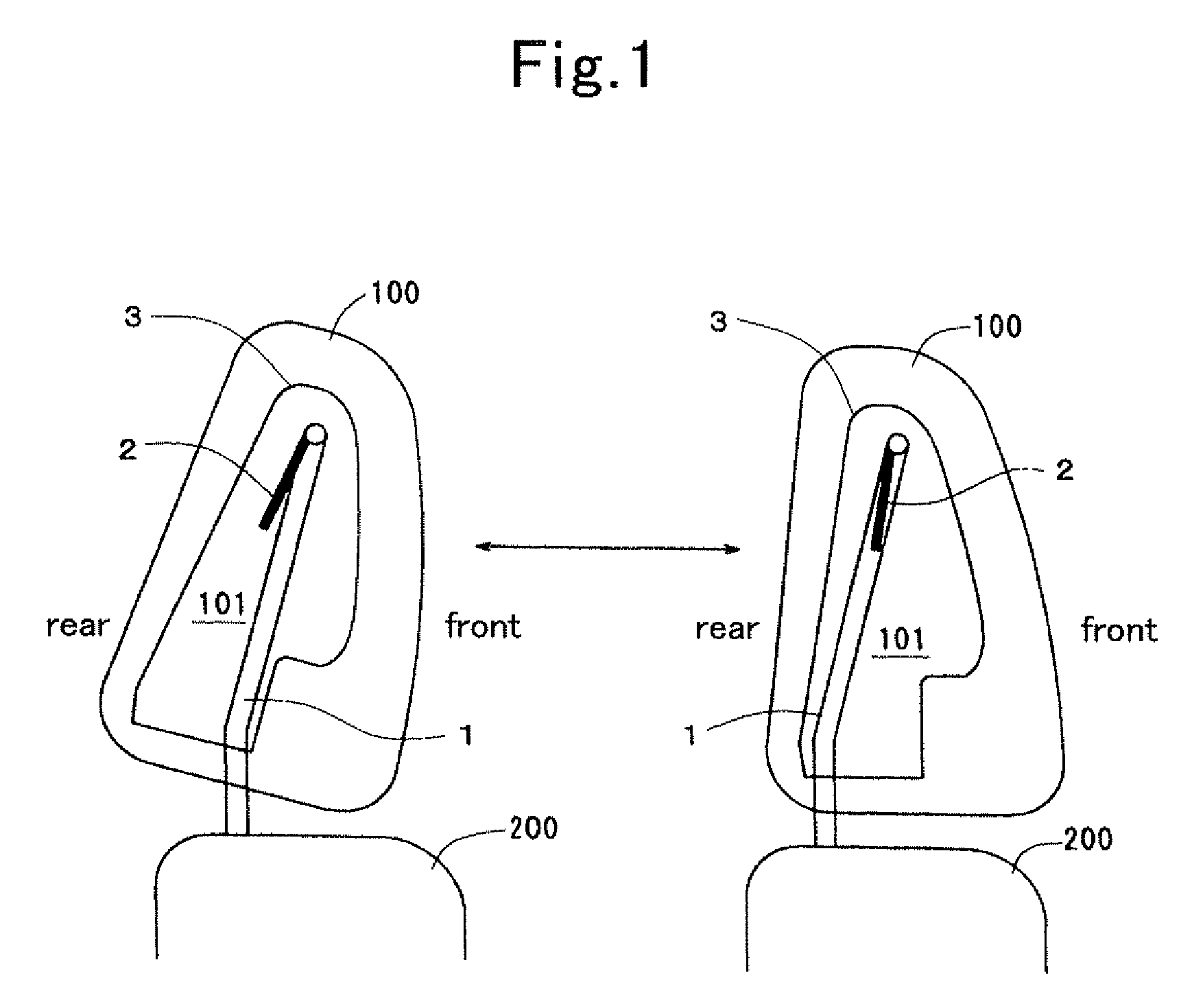
[0050]FIG. 1 is an explanatory view explaining the operation of the head rest apparatus of an embodiment. The head rest apparatus includes a metal stay 1, a metal plate 2 and a core member 3 housed in a head rest main body 100. The metal stay 1 is inserted into a seat back 200 and secured thereto. The metal plate 2 is rotatably supported on the horizontal rod of the metal stay 1 with a frictional resistance and fixed to the core member 3. A space 101 is provided within the core member 3 for allowing the movement of the leg portions of the metal stay 1 therein.

[0051]Accordingly, according to this head rest apparatus, by swinging or rotating the core member 3 and the metal plate 2 through the head rest main body 100, the position of the head rest in a front / rear direction can be adjusted as viewed in FIG. 1.

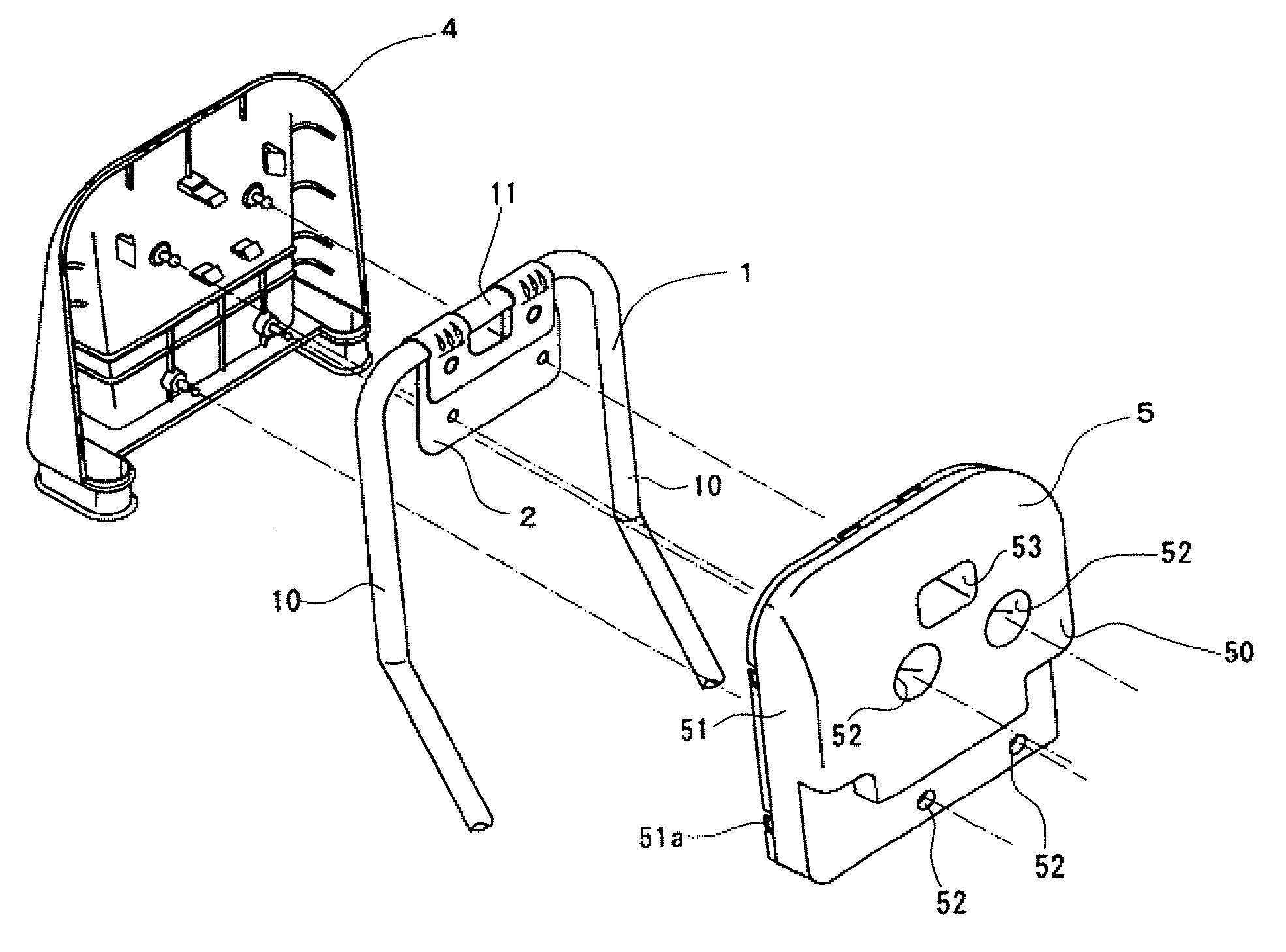
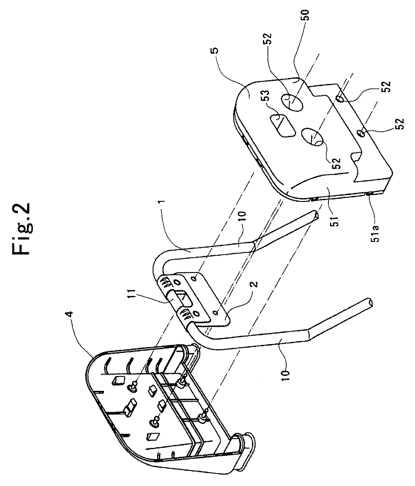
[0052]As shown in FIG. 2, the metal stay 1 has a reverse U-shape formed by a pair of leg portions 10 extending in approximately parallel with each other having a space therebetween...

embodiment 2

[0064]FIG. 9 shows a cross sectional view of the main part of the head rest apparatus according to this embodiment. The head rest apparatus of this embodiment is structured similar to that of the previous embodiment excepting that the upper two second connecting pins 52 among the four second connecting pins 52 of the second divided body 5 are separated from the front side surface of the flat plate portion 21. In this structure, the flat plate portion 21 is also tightly fixed to the first divided body 4 and the stress applied from the flat plate portion 21 upon rotation of the head rest main body 100 acts only on the first divided body 4 and the stress is absorbed within the first divided body 4 not to loosen the connection of the first divided body with the second divided body 5.

embodiment 3

[0065]FIG. 10 shows a cross sectional view of the main part of the head rest apparatus according to this embodiment. The head rest apparatus of this embodiment is structured similar to the first embodiment, excepting that instead of providing the second holding pawls 44, a projection 48 having a tapered portion 48a is provided. In this structure, the flat plate portion 21 is in contact with the pair of holding pawls 43 between the front surface of rib 47 and the stepped portion 45a of the first connecting pin 45 and is tightly fixed with three supporting points, and therefore, the stress applied from the flat plate portion 21 upon rotation of the head rest main body 100 acts only on the first divided body 4 and the stress is absorbed within the first divided body 4 to prevent generation of abnormal noise and rattling in operation.

[0066]It is noted that the head rest apparatus structured by combining the head rest apparatus according to the second embodiment with the head rest appara...


PUM


Abstract

In the head rest apparatus, a core member is separately formed from a metal plate and a metal stay, wherein a fixing member is integrally formed on a first divided body of the core member and the fixing member mechanically engages the flat plate portion of the metal plate with the first divided body and fixes the flat plate portion to the first divided body. The flat plate position is tightly fixed to the first divided body. Since the stress can be absorbed only by the first divided body, generation of abnormal noise can be prevented without using any damper member and in addition, rattling in operation can be prevented as well.

Description

TECHNICAL FIELD[0001]This invention relates to a head rest apparatus adapted to be used by being supported on a seat back or the like of an automobile, and more particularly, a head rest apparatus, the position of which is adjustable in a front / rear direction considering the head position of an occupant of the automobile by swinging or rotating a main body of the head rest apparatus relative to a metal stay.BACKGROUND OF THE TECHNOLOGY[0002]As an example of the head rest apparatus of the type above, a head rest apparatus is disclosed in a Japanese Patent Publication 2002-000388 A. The head rest apparatus according to this publication includes an approximately reverse U-shaped metal stay formed by a pair of vertical support rod portions supported on the seat back and a horizontal support rod portion connecting both ends of the pair of vertical support rod portion, respectively, a metal plate rotatably supported on the horizontal support rod portion, having a pre-set frictional force ...

Claims


Application Information

Patent Timeline
Patent Type & Authority Patents(United States)
IPC IPC(8): A47C7/38
CPCB60N2/485B60N2205/20B60N2/85A47C7/38
Inventor FUJITA, MASARU
Owner TOKAI CHEM IND CO LTD
Why Eureka
Try Eureka