Imaging lens

a technology of imaging lens and image, applied in the field of imaging lens, can solve the problems of not meeting the recent demands for miniaturization, difficult to achieve miniaturization and high resolution, and difficult to satisfactorily correct each aberration, etc., to achieve satisfactorily correct aberrations, high imaging performance, and reduce distortion

a technology of imaging lens and image, applied in the field of imaging lens, can solve the problems of not meeting the recent demands for miniaturization, difficult to achieve miniaturization and high resolution, and difficult to satisfactorily correct each aberration, etc., to achieve satisfactorily correct aberrations, high imaging performance, and reduce distortion

US8416510B2Inactive Publication Date: 2013-04-09OPTICAL LOGIC

Image

  • Imaging lens
  • Imaging lens
  • Imaging lens

Examples


Embodiment Construction

[0051]Hereunder, referring to the accompanying drawings, an embodiment of the present invention will be fully described.

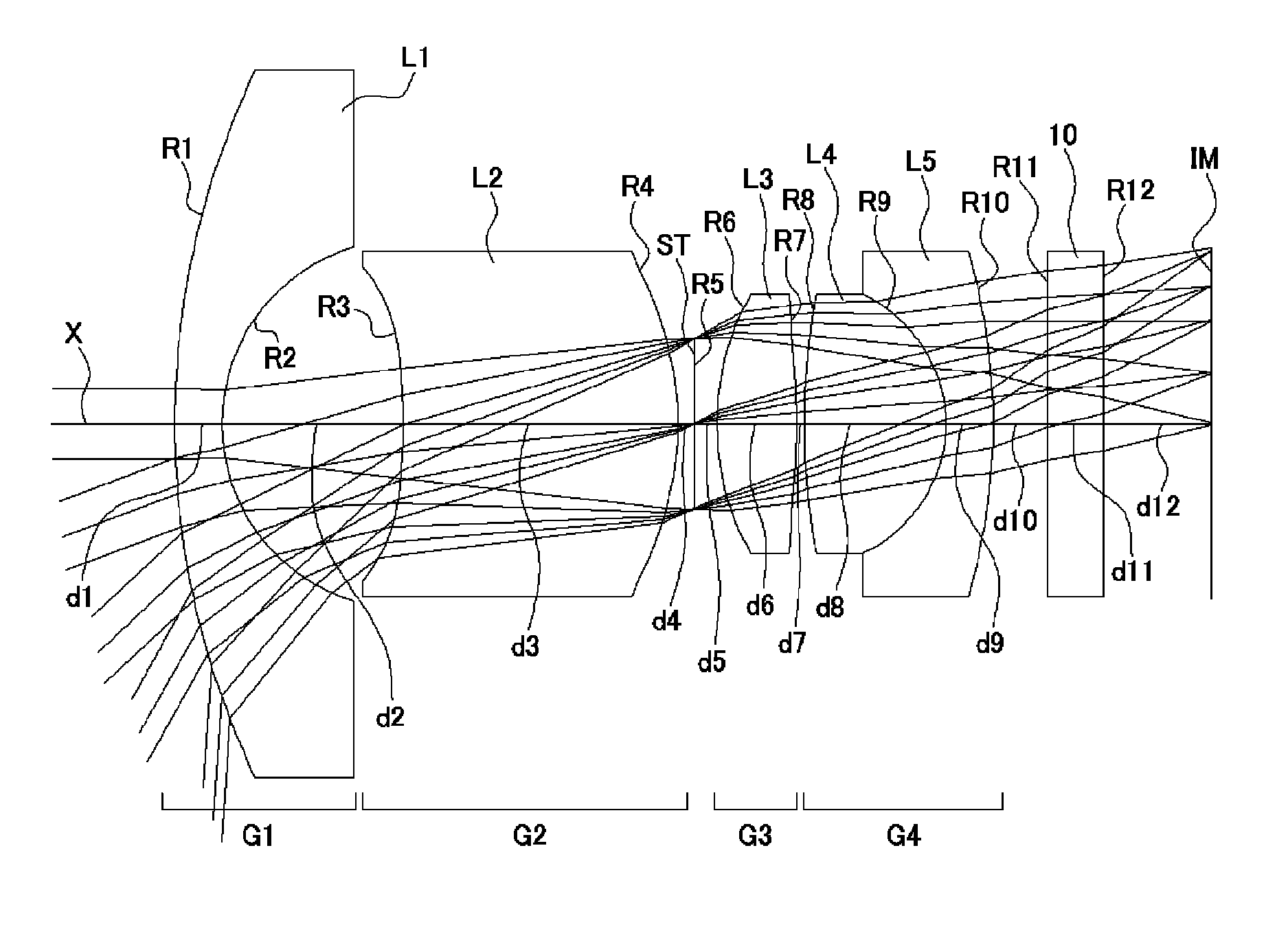
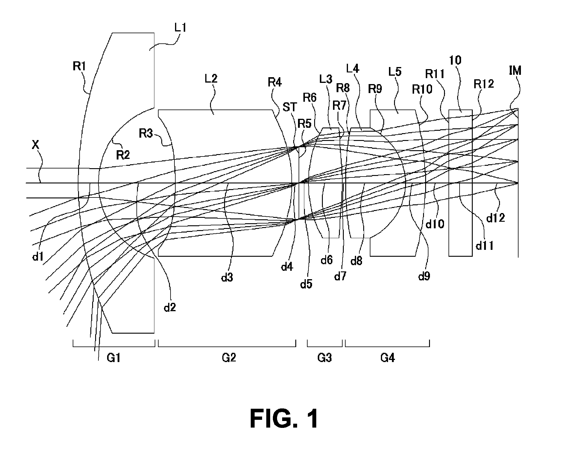
[0052]FIGS. 1, 4, 7, 10, and 13 are sectional views of image lenses in Numerical Data Examples 1 to 5 according to the embodiment, respectively. Since a basic lens configuration is the same among the Numerical Data Examples 1 to 5, the lens configuration of the embodiment will be described with reference to the lens sectional view of Numerical Data Example 1.

[0053]As shown in FIG. 1, the imaging lens of the embodiment has an first lens group G1 having negative refractive power; a second lens group G2 having positive refractive power; an aperture stop ST; a third lens group G3 having positive refractive power; and a fourth lens group G4, arranged in this order from an object side to an image side of the imaging lens. A filter 10 is provided between the fourth lens group G4 and the image plane IM. Here, the filter 10 may be optionally omitted.

[0054]The first lens gro...


PUM


Abstract

An imaging lens includes a first lens group having a first lens that directs a concave surface to an image plane side and is negative; a second lens group having a second lens that directs a concave surface to an object side and is positive; an aperture; a third lens group having a third lens that is positive; and a fourth lens group having a joined lens that is composed of a fourth lens that is positive and a fifth lens that is negative. In the configuration, when the whole lens system has a focal length f and a composite focal length of the first lens group to the third lens group is Fa, the imaging lens satisfies the following relation:0.3<f / Fa<1.0.

Description

BACKGROUND OF THE INVENTION AND RELATED ART STATEMENT[0001]The present invention relates to an imaging lens for forming an image on an imaging element such as a CCD sensor and a CMOS sensor. In particular, the present invention relates to an imaging lens suitable for mounting in a relatively small camera such as a cellular phone, a digital still camera, a portable information terminal, a security camera, an onboard camera, and a network camera.[0002]In these years, for a purpose of improving convenience and security, a plurality of cameras is mounted on a vehicle. For example, a vehicle may be equipped with a back camera to take a picture of a backside of the vehicle. In this case, a driver can see a situation behind the vehicle through a monitor when the vehicle is pulled back, so that even when there is an obstacle that is hard to see due to a blind side of the vehicle, it is possible to safely pull the vehicle back without contacting such an obstacle. There has been an expectatio...

Claims


Application Information

Patent Timeline
09 Apr 2013
Publication
US8416510B2
IPC
G02B13/04; G02B9/58; G02B9/34; H04N5/225
CPC
G02B3/04; G02B13/004; G02B9/58
Inventors
KUBOTA, YOJI; KUBOTA, KENICHI