Load control system having an energy savings mode

a technology of load control and energy saving, applied in the field of load control system, can solve the problems of significant increase in the total power cost of the electric consumer, and achieve the effect of reducing the power consumption of the heating and cooling system

Active Publication Date: 2013-04-09
LIT MOTORS +1
View PDF99 Cites 105 Cited by
  • Summary
  • Abstract
  • Description
  • Claims
  • Application Information

AI Technical Summary

Problems solved by technology

Thus, if an electricity consumer consumes power at a very high rate for only a short period of time, the electricity consumer will face a significant increase in its total power costs.

Method used


Image

  • Load control system having an energy savings mode
  • Load control system having an energy savings mode
  • Load control system having an energy savings mode

Examples


first embodiment

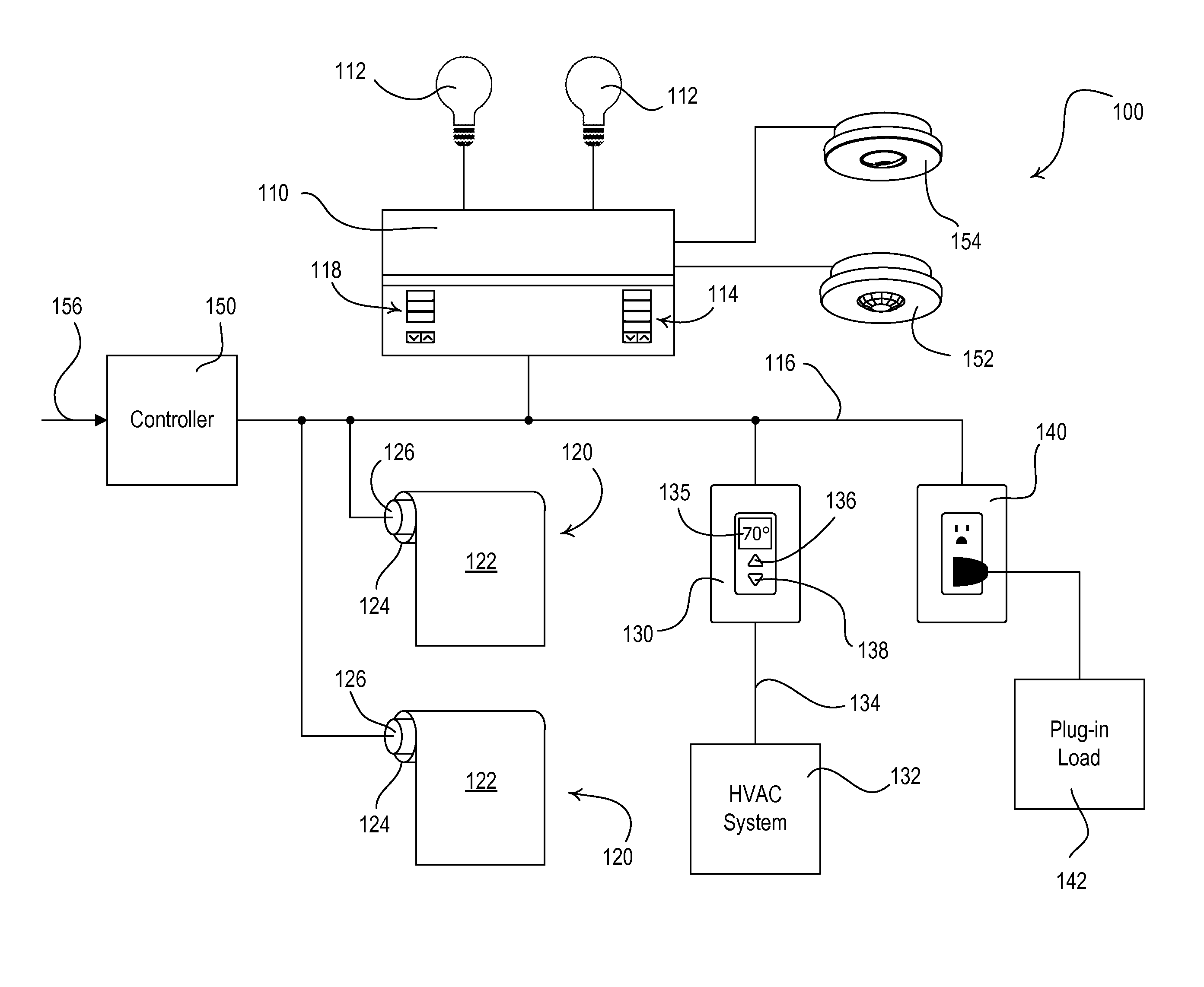
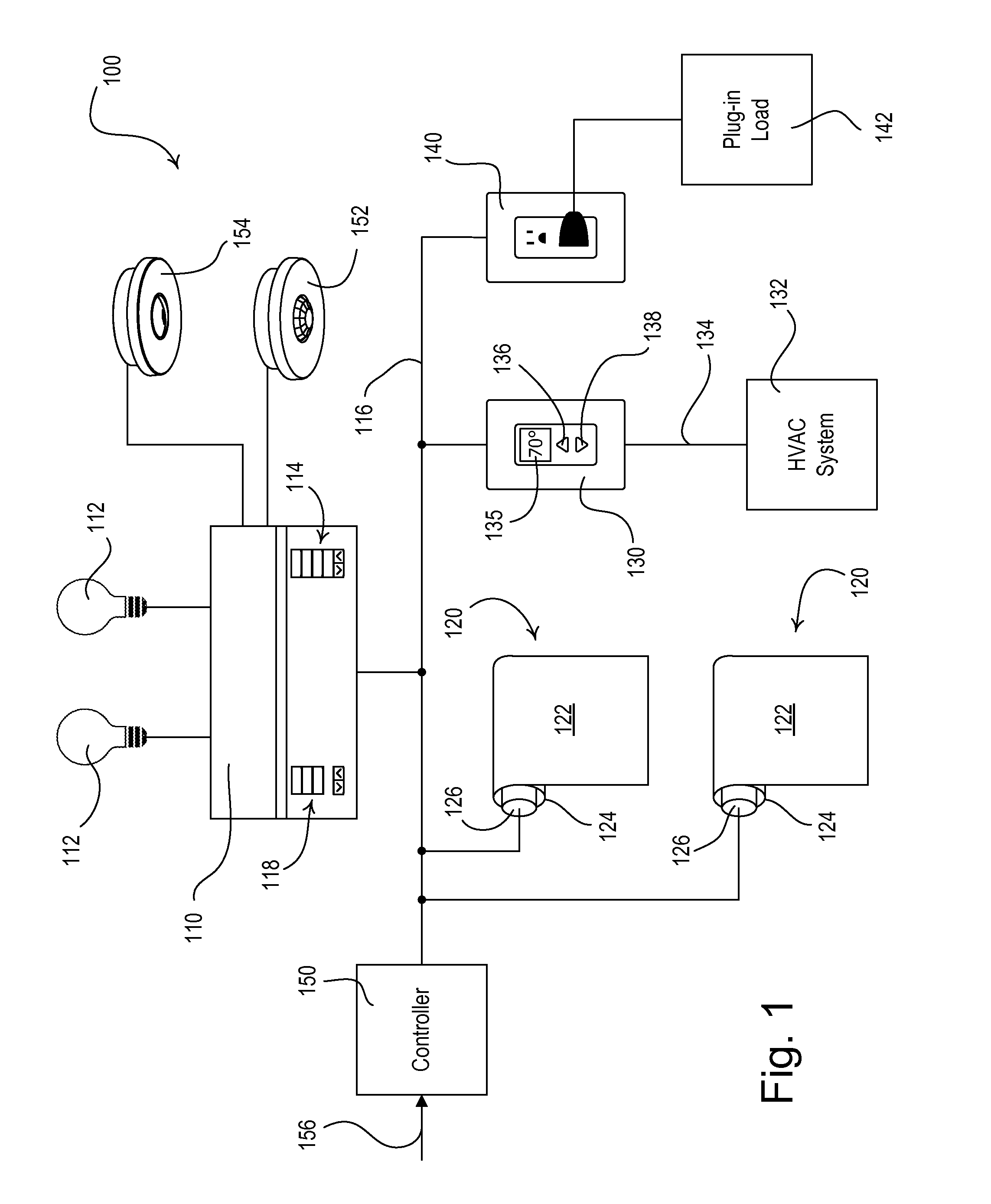
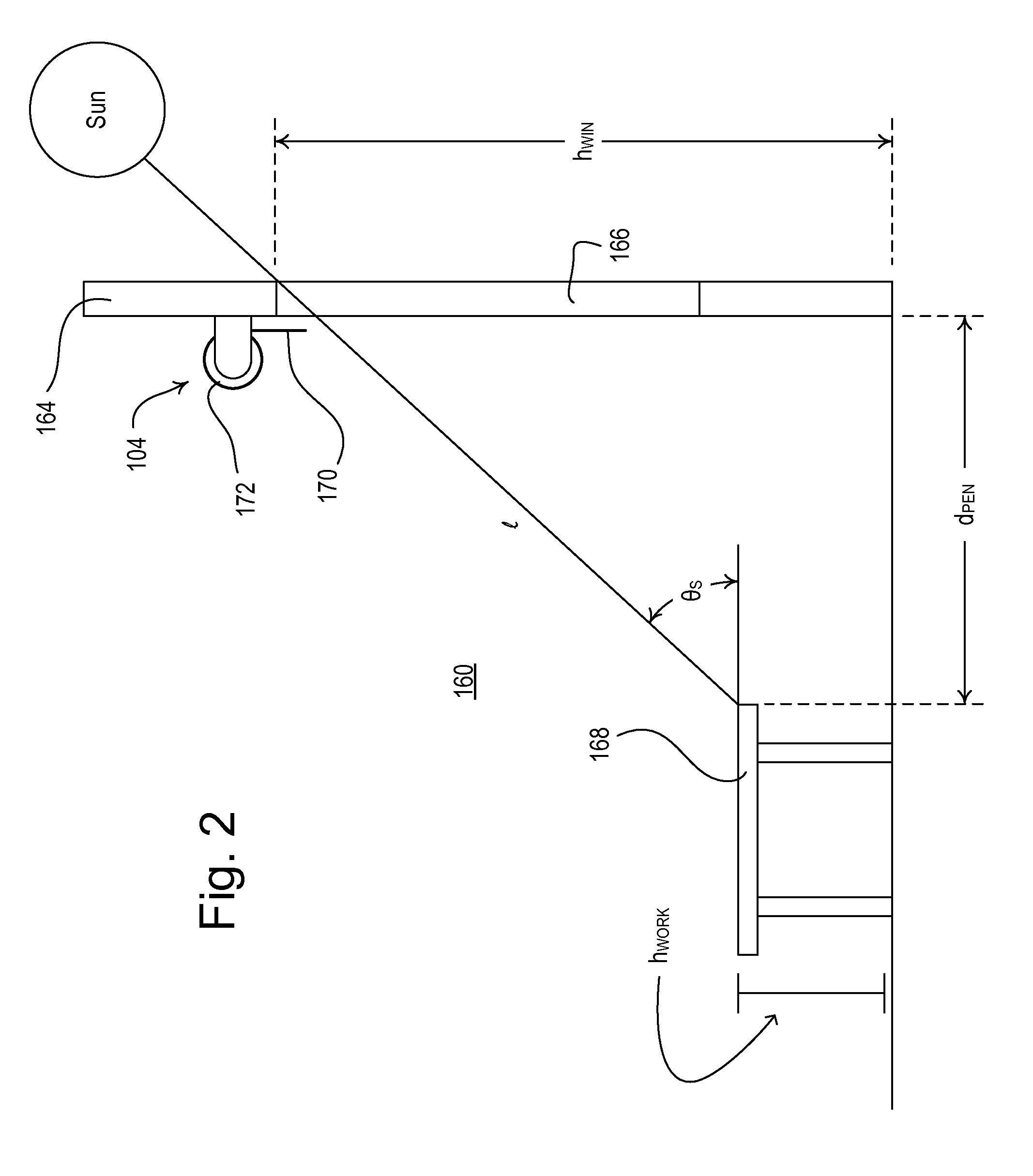
[0045]FIG. 1 is a simplified block diagram of a centralized load control system 100 that may be installed in a building (such as a commercial building) according to the present invention. The load control system 100 comprises a multi-zone lighting control device 110 that is operable to control the amount of power delivered from an alternating-current (AC) power source (not shown) to one or more lighting loads 112 for adjusting the intensities of the lighting loads. The lighting load 112 may be located in a space 160 (FIG. 2) of the building to thus control the amount of electric light (i.e., artificial light) in the space. The lighting loads 112 may comprise, for example, incandescent lamps, halogen lamps, gas discharge lamps, fluorescent lamps, compact fluorescent lamps, high-intensity discharge (HID) lamps, magnetic low-voltage (MLV) lighting loads, electronic low-voltage (ELV) lighting loads, light-emitting diode (LED) light sources, hybrid light sources comprising two or more di...

second embodiment

[0111]FIG. 16 is a simplified flowchart of a planned demand response procedure 1200 executed by the controller 150 of the load control system 100 according to the present invention. In response to receiving a planned demand response command, the controller 150 controls the load control system 100 to reduce the total power consumption at a predetermined start time tSTART in the future, for example, at noon on the day after the planned demand response command was received. The controller 150 is operable to “pre-condition” (i.e., pre-cool or pre-heat) the building before the start time tSTART of the planned demand response command, such that the HVAC system 132 will be able to consume less power during the planned demand response event (i.e., after the start time). To pre-condition the building before a planned demand response event, the controller 150 is operable to pre-cool the building when the HVAC system 132 is in the cooling mode and will be cooling the building during the presen...

third embodiment

[0118]According to the present invention, the controller 150 is operable to control the lighting control device 110, the motorized roller shades 120, the temperature control device 130, and the controllable electrical receptacle 140 according to a plurality of demand response (DR) levels. A demand response level is defined as a combination of predetermined parameters (e.g., lighting intensities, shades positions, temperatures, etc.) for one or more of the loads of the load control system 100. The demand response levels provide a number of predetermined levels of energy savings that the load control system 100 may provide in response to the demand response command. For example, in a specific demand response level, a certain number of lighting loads may be dimmed by a predetermined amount, a certain number of motorized roller shades may be closed, a certain number of plug-in electrical loads 142 may be turned off, and the setpoint temperature may be adjusted by a certain amount. The d...


PUM


Abstract

A load control system for a building having a heating and cooling system and a window located in a space of the building is operable to control a motorized window treatment in response to a demand response command in order to attempt to reduce the power consumption of the heating and cooling system. When the window may be receiving direct sunlight, the motorized window treatment closes a fabric covering the window when the heating and cooling system is cooling the building, and opens the fabric when the heating and cooling system is heating the building. In addition, when the space is unoccupied and the heating and cooling system is heating the building, the motorized window treatment may open the fabric if the window may be receiving direct sunlight, and may close the fabric if the window may not be receiving direct sunlight.

Description

CROSS REFERENCE TO RELATED APPLICATIONS[0001]The present application is a non-provisional application of commonly-assigned, U.S. Provisional Patent Application No. 61 / 230,001, filed Jul. 30, 2009, and U.S. Provisional Application No. 61 / 239,988, filed Sep. 4, 2009, both entitled LOAD CONTROL SYSTEM HAVING AN ENERGY SAVINGS MODE, the entire disclosures of which are hereby incorporated by reference.BACKGROUND OF THE INVENTION[0002]1. Field of the Invention[0003]The present invention relates to a load control system for a plurality of electrical loads in a building, and more particularly, to a load control system for controlling the lighting intensities of lighting loads, the positions of motorized window treatments, and the temperature of the building in order to reduce the total power consumption of the load control system.[0004]2. Description of the Related Art[0005]Reducing the total cost of electrical energy is an important goal for many electricity consumers. The customers of an ...

Claims


Application Information

Patent Timeline
Patent Type & Authority Patents(United States)
IPC IPC(8): G05B13/00
CPCE06B9/68F24F11/0009G05D23/1919H05B37/0218G05B11/01E06B9/02E06B9/24E06B9/40E06B2009/6818F24F11/0012F24F11/0034F24F2011/0049F24F2011/0056F24F2011/0075Y02B20/40Y02B20/46F24F11/30F24F2110/10F24F2120/10F24F2130/20F24F2140/40F24F11/46H05B47/11F24F11/58F24F2120/00F24F11/47F24F11/63
Inventor ALTONEN, GREGORYFRICKE, WILLIAM BRYCEJACOBY, ELLIOT G.PESSINA, MICHAEL W.ZAHARCHUK, WALTER S.SPIRA, JOEL S.
Owner LIT MOTORS
Why Eureka
Try Eureka