Electromagnetic proportional flow rate control valve

a flow rate control valve and proportional flow technology, applied in process and machine control, servomotors, instruments, etc., can solve problems such as difficult accurate flow rate control, and achieve the effects of improving flow rate control precision, reducing valve opening degree, and reducing the number of valves

Inactive Publication Date: 2013-04-16
OKI ELECTRIC IND CO LTD
View PDF37 Cites 15 Cited by
  • Summary
  • Abstract
  • Description
  • Claims
  • Application Information

AI Technical Summary

Benefits of technology

[0010]According to the present invention, a solenoid driving force with respect to a valve stroke is given such characteristics that there is a drop off on an adsorption side for an identical driving current, that is, a valve opening degree is made smaller. Thus, compared with a case of flat characteristics described above, an amount of change in an area of the valve opening is small with respect to unit changes in the driving current in a region where the stroke of the valve member is short, with the result that flow rate control precision is increased in a low flow rate control region.
[0011]Further, according to the present invention, the electromagnetic proportional flow rate control valve is structured such that the proportion of reduction in the area of the opening of a variable orifice gradually becomes smaller with respect to the valve stroke as the valve member approaches a valve seat. Thus, the flow rate control precision is increased in the low flow rate control region.

Problems solved by technology

A problem consequently developed in that accurate flow rate control becomes difficult in a low flow rate region where the flow rate to be controlled is small.

Method used


Image

  • Electromagnetic proportional flow rate control valve
  • Electromagnetic proportional flow rate control valve
  • Electromagnetic proportional flow rate control valve

Examples


Embodiment Construction

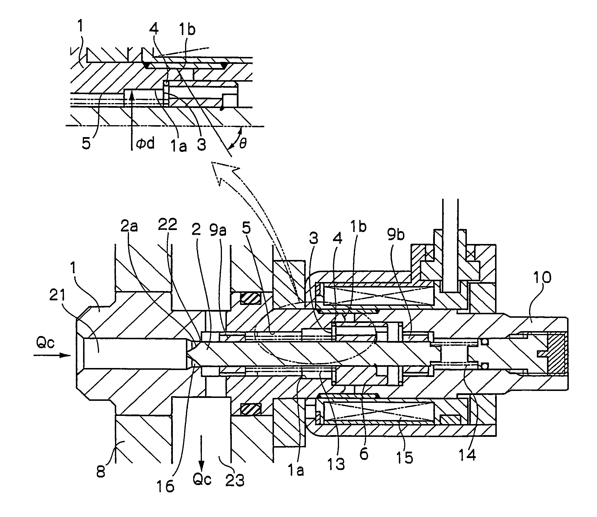
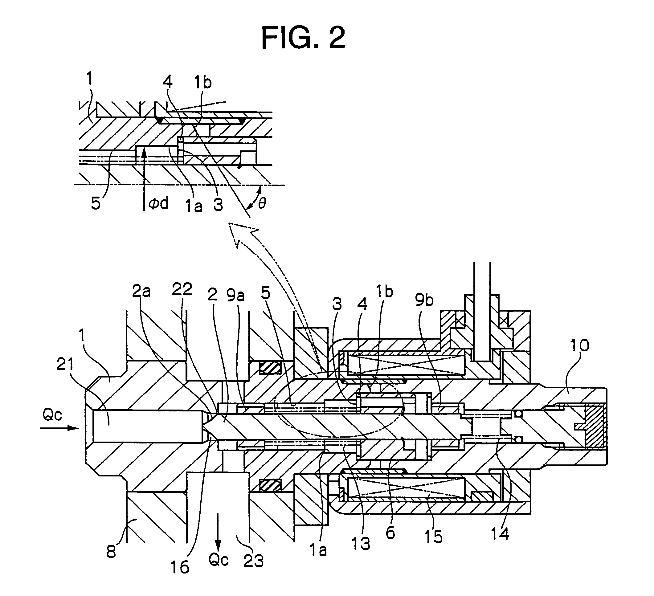
[0020]An embodiment of this invention will be described hereinbelow with reference to the drawings.

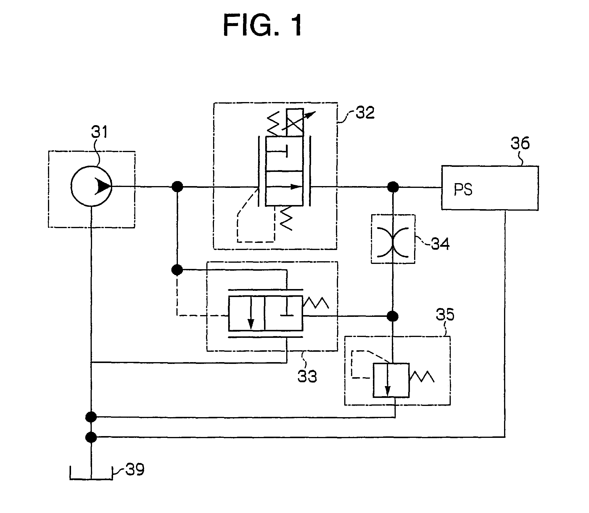
[0021]FIG. 1 is a hydraulic circuit diagram of a power steering apparatus for automobiles.

[0022]Reference numeral 31 denotes a pump. Hydraulic oil discharged from the pump 31 is supplied to a power steering system 36 for assisting steering operations in an automobile. An electromagnetic proportional flow rate control valve 32 is provided in order to control the flow rate of the hydraulic oil supplied to the power steering system 36.

[0023]The flow rate of the hydraulic oil controlled by the electromagnetic proportional flow rate control valve 32 is proportional to the valve opening degree of the electromagnetic proportional flow rate control valve 32, and to a pressure difference between an upstream and downstream of the valve. Accordingly, if the pressure difference is constant, the flow rate is changed depending upon solely the opening degree of the valve 32. Accordingly, in order to ...


PUM


Abstract

An electromagnetic proportional flow rate control valve capable of performing precise flow rate control in a low flow rate side of an operating region is provided. In an electromagnetic proportional flow rate control valve 32, in which a valve member 2 is driven in a valve closing direction in accordance with the increase in a driving current I of a solenoid coil 15, a solenoid driving force F is set such that it decreases accompanying the displacement of the valve member 2 in the valve closing direction with respect to an identical driving current in the solenoid coil 15. Thus, an amount of change in an area of a valve opening with respect to unit changes in the driving current I becomes smaller in a region at which the stroke is small compared to a case of having flat characteristics, whereby the flow rate control precision in the low flow rate region can be improved.

Description

TECHNICAL FIELD[0001]This invention relates to an improvement of an electromagnetic proportional flow rate control valve used for power steering apparatuses of automobiles, industrial machines, and the like.BACKGROUND ART[0002]The device disclosed in Japanese Patent Application Laid-open No. 2001-163233, for example, is a conventional electromagnetic proportional flow rate control valve used for power steering apparatuses.[0003]In the electromagnetic flow rate control valve described above, as shown by dashed lines in FIG. 3, a driving force of a solenoid for driving a valve member is set to have flat characteristics so that the solenoid driving force becomes uniform over nearly an entire region of a valve stroke with respect to an identical driving current.[0004]In general, as shown by double dashed lines in FIG. 3, the solenoid driving force sharply increases on an adsorption side in accordance with a valve stroke with respect to an identical driving current. However, since contro...

Claims


Application Information

Patent Timeline
Patent Type & Authority Patents(United States)
IPC IPC(8): F16K31/06B62D5/06B62D5/065F15B11/05G05D7/06
CPCB62D5/062B62D5/065F15B11/055F16K31/0655F16K31/0675G05D7/06F15B2211/40507F15B2211/40515F15B2211/40561F15B2211/40576F15B2211/413F15B2211/41563F15B2211/41572F15B2211/426F15B2211/428F15B2211/45F15B2211/455F15B2211/50518F15B2211/5157F15B2211/55G05D7/0641Y10T137/86622
Inventor TSUCHIYA, HIDEKIMIYA, YOSHIHARU
Owner OKI ELECTRIC IND CO LTD
Why Eureka
Try Eureka