Regenerative building block and diode bridge rectifier and methods

a diode bridge rectifier and building block technology, applied in the field of regenerative building block and diode bridge rectifiers, can solve the problems of small improvement space through conventional techniques, inefficient diodes, and close to the theoretical limit of diodes, so as to avoid the complexity of control signals of conventional synchronous rectifiers, the effect of improving the performance of diodes

Active Publication Date: 2013-04-16
STMICROELECTRONICS INT NV
View PDF153 Cites 14 Cited by
  • Summary
  • Abstract
  • Description
  • Claims
  • Application Information

AI Technical Summary

Benefits of technology

[0009]A regenerative building block (RBB) is proposed as a new semiconductor device, which in particular can be used in pairs to make efficient diode half bridges capable of operating at low voltages without unacceptable loss. Each RBB has 4 electrodes: source, drain, gate and probe. In an embodiment, the current between the source and drain of each RBB can be controlled by the gate voltage. The probe electrode of the first RBB provides the regenerative signal for the gate electrode of the second RBB. This signal from the probe electrode can be used to switch an adjacent semiconductor device, forming the second device of the pair, between ON and OFF states. Thus, a half bridge made with a pair of RBB's in accordance with the invention has only three external contacts. An embodiment of a half bridge having a common anode or common cathode made from two RBB's exhibits better than ideal diode performance similar to synchronous rectifiers. Since the half bridge requires only three contacts, the control signal complexity of conventional synchronous rectifiers is avoided.

Problems solved by technology

This switching of the current flow between the two diodes results in rectification.
Some diodes are close to this theoretical limit, leaving very small space for improvement through conventional techniques.
This theoretical limit leads to very inefficient diodes once the electronics moves to lower voltages.
This high energy loss just for the rectification is unacceptable for modern switched-mode power supplies.
However, the circuit implementation of synchronous rectification becomes very complicated.
This additional signal processing reduces the speed of operation for half bridges made of synchronous rectifiers.
Thus instead of 2 diodes, one needs a much more complicated and expensive circuit.

Method used


Image

  • Regenerative building block and diode bridge rectifier and methods
  • Regenerative building block and diode bridge rectifier and methods
  • Regenerative building block and diode bridge rectifier and methods

Examples


Embodiment Construction

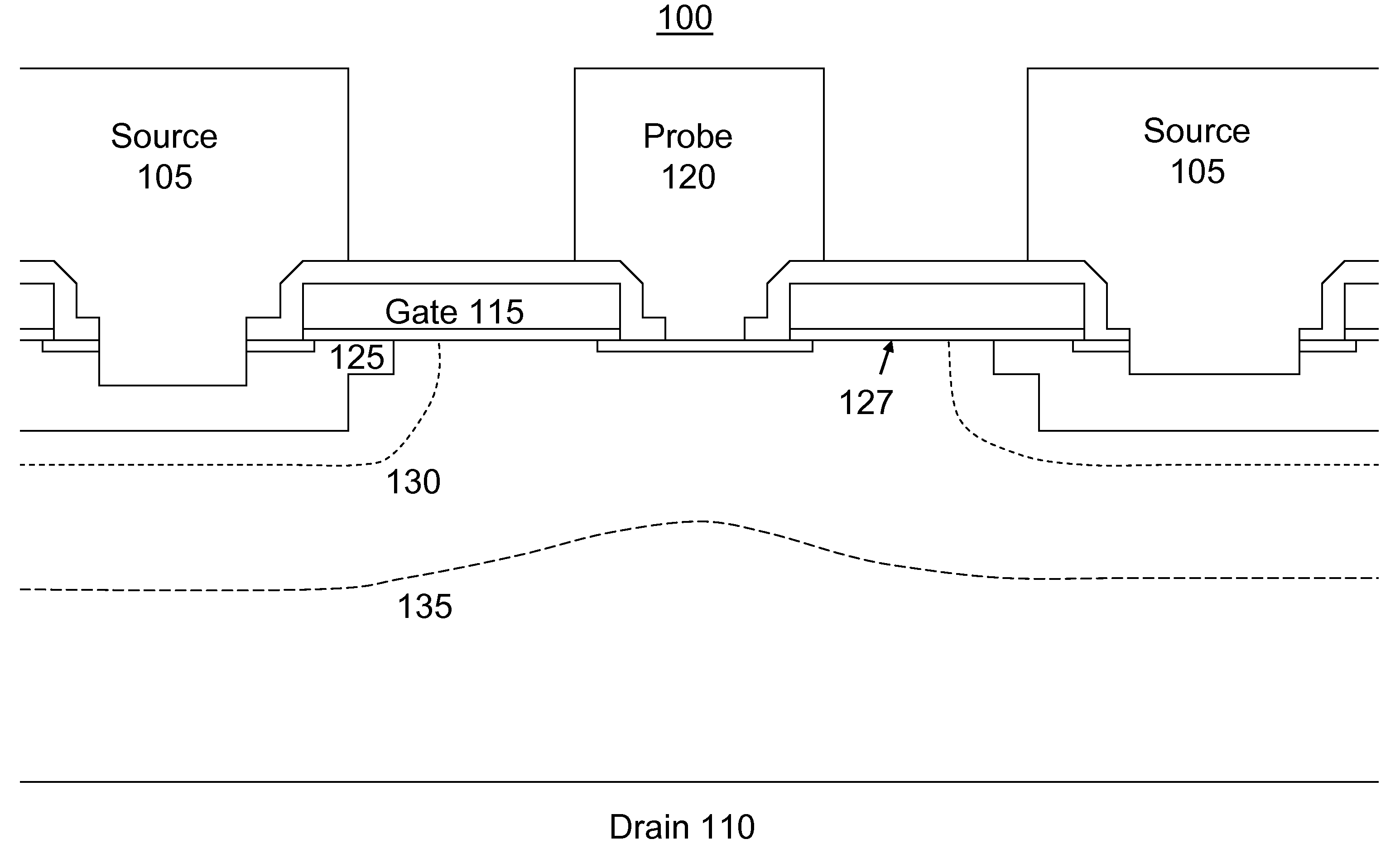
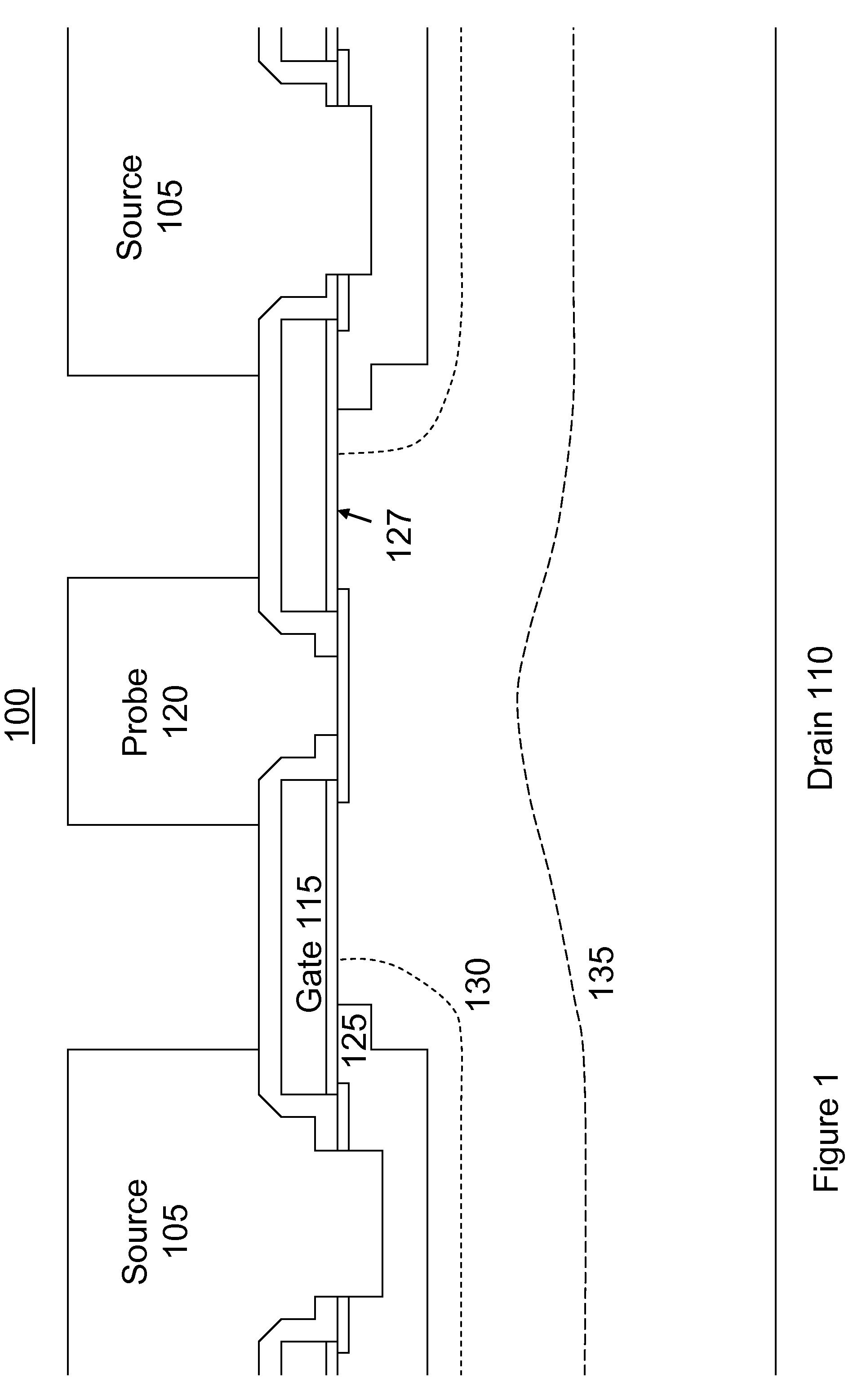
[0029]The present invention comprises a new device which can be thought of as a regenerative building block (RBB), and methods of manufacture therefore. In an embodiment, the device is particularly suited to fabrication of devices such as half bridge and full bridge rectifiers. Although those skilled in the art will quickly recognize that the present invention can be used to create a variety of semiconductor devices, for purposes of clarity the present invention will be described in the context of a bridge rectifier, both as a device and as a method of manufacture.

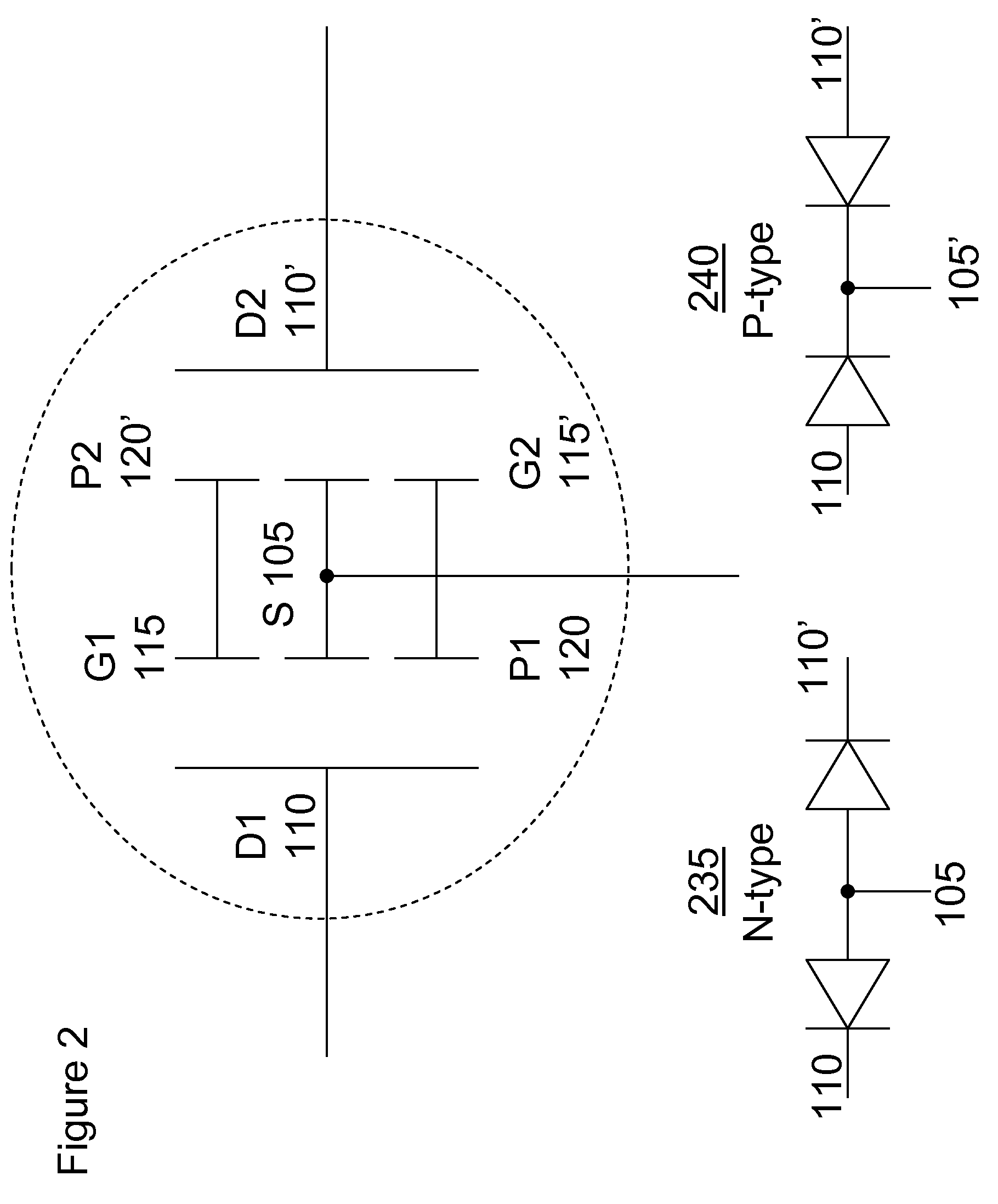
[0030]Referring first to FIGS. 1 and 2, the RBB structure indicated generally at 100 is shown both in terms of its physical structure (FIG. 1) and its schematic representation in a pair configured as a half bridge rectifier (FIG. 2). As shown in FIG. 1, the RBB 100 has four electrodes: source 105, drain 110, gate 115 and probe 120. The main current flows between the source and drain electrodes. The gate voltage controls th...


PUM


Abstract

A rectifier building block has four electrodes: source, drain, gate and probe. The main current flows between the source and drain electrodes. The gate voltage controls the conductivity of a narrow channel under a MOS gate and can switch the RBB between OFF and ON states. Used in pairs, the RBB can be configured as a three terminal half-bridge rectifier which exhibits better than ideal diode performance, similar to synchronous rectifiers but without the need for control circuits. N-type and P-type pairs can be configured as a full bridge rectifier. Other combinations are possible to create a variety of devices.

Description

RELATED APPLICATIONS[0001]This application is related to, and claims the benefit of U.S. Provisional Patent Application Ser. No. 61 / 022,968, filed Jan. 23, 2008, as well as U.S. patent application Ser. No. 12 / 238,308, filed Sep. 25, 2008, and, through it, claims the benefit of U.S. Provisional Patent Application Ser. No. 60 / 975,467, filed Sep. 26, 2007, entitled Adjustable Field Effect Rectifier, and commonly assigned.FIELD OF THE INVENTION[0002]The present invention relates generally to semiconductor rectifiers, and more specifically to a regenerative self-controlling mechanism for improving the performance of diode bridges, and methods therefor.BACKGROUND OF THE INVENTION[0003]Diode bridges, either full or half bridges, are very common circuit elements to perform rectification of oscillating output signal. A half bridge is made of two diodes and has three external electrodes. They are commonly used for the output rectification in switched-mode power supply circuits: e.g. in forwar...

Claims


Application Information

Patent Timeline
Patent Type & Authority Patents(United States)
IPC IPC(8): H01L29/66H01L21/332
CPCH01L29/66075H01L27/0817H01L29/861H01L29/78H01L29/66477H01L29/7802H01L29/0646
Inventor ANKOUDINOV, ALEXEIRODOV, VLADIMIR
Owner STMICROELECTRONICS INT NV
Why Eureka
Try Eureka