
Arrangement of stringed solenoid drives

a technology of stringed solenoid drives and drives, which is applied in the direction of electrical equipment, valve details, electrical motors, etc., can solve the problems of magnetic flux, loss of energy, and greater extent of undesirable mutual influence of magnetic circuits, so as to reduce leakage flux and apply minimum energy

Active Publication Date: 2013-04-16
BURKERT WERKE
View PDF12 Cites 0 Cited by
  • Summary
  • Abstract
  • Description
  • Claims
  • Application Information

AI Technical Summary

Benefits of technology

[0005]The arrangement according to the invention serves to reduce the leakage flux to neighboring magnetic circuits and allows a reliable switching of solenoid valves disposed in an in-line array, with a minimum amount of energy applied.
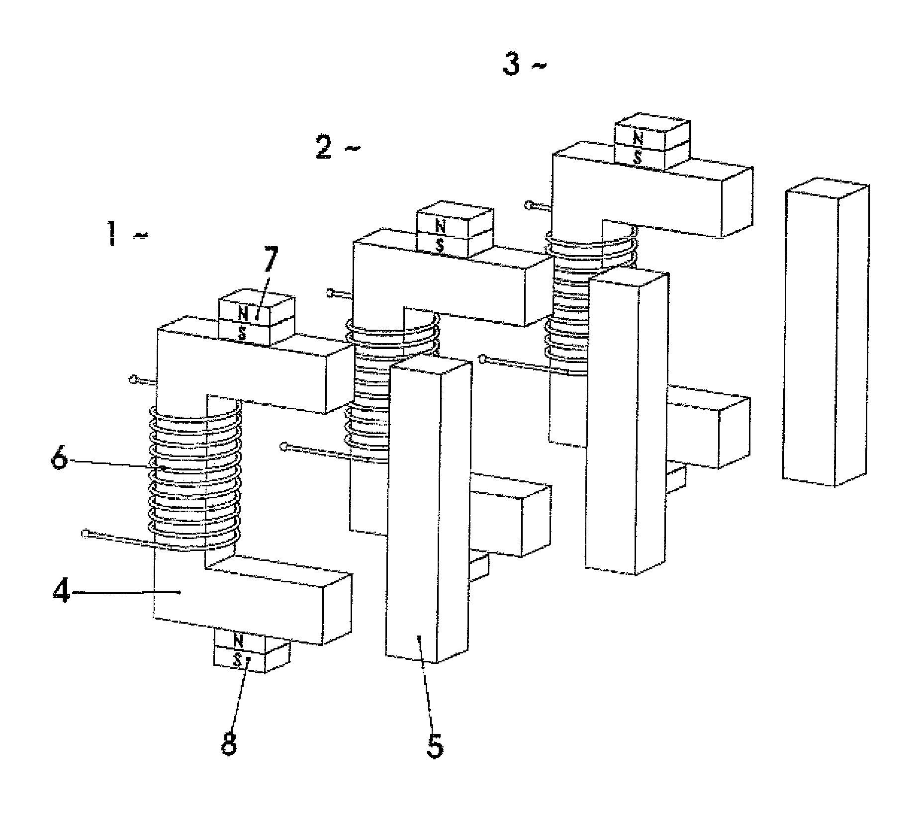
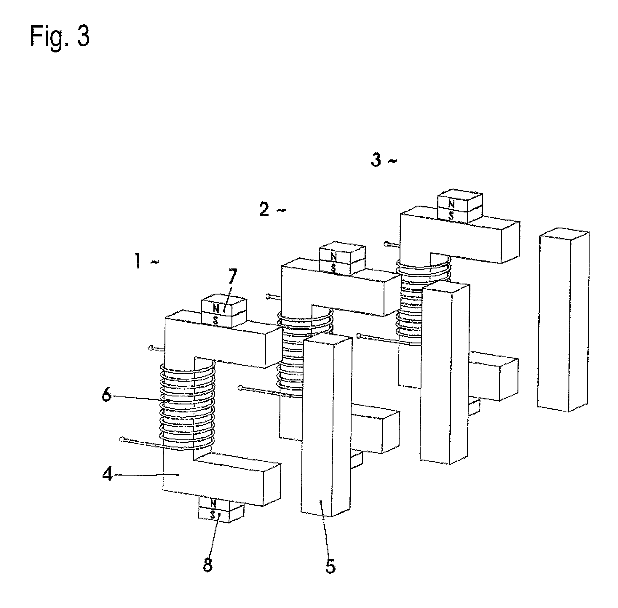
[0006]Specifically, the invention provides an in-line array of closely spaced solenoid drives in which each solenoid drive includes a magnetic circuit with a yoke, a movable armature, and an excitation winding disposed on the yoke. The magnetic circuits of adjacent solenoid drives have a pre-magnetization of same magnetic polarity and of at least approximately same strength as a magnetization caused by current flow in the excitation winding of each solenoid drive. The pre-magnetization causes the magnetic potential difference between neighboring magnetic circuits to be reduced. The pre-magnetization is thus effected with the same polarity as the excitation by current flow in the excitation winding.

Problems solved by technology

The smaller the solenoid valves in terms of their outer dimensions and the closer they are to be arranged next to each other for reasons of space, the greater the extent of undesirable mutual influence of the magnetic circuits on each other.
This is accompanied by losses of energy.
Magnetic flux does not stay within an apparatus, but flows off, ineffective in terms of power for this apparatus, via neighboring, magnetically conductive metal parts or is redirected to neighboring magnetic circuits.
In the most unfavorable case, it may happen that a valve is unintentionally also switched when its neighboring valve switches.

Method used


Image

  • Arrangement of stringed solenoid drives
  • Arrangement of stringed solenoid drives
  • Arrangement of stringed solenoid drives

Examples


Embodiment Construction

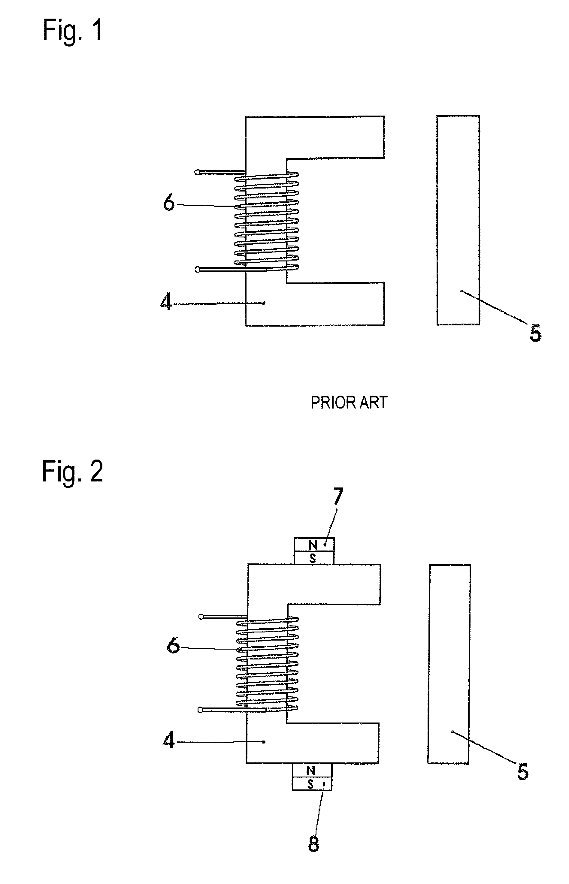
[0019]A conventional magnetic circuit as shown in FIG. 1 is comprised of a U-shaped yoke 4, a winding 6 and an armature 5.

[0020]The magnetic circuit in FIG. 2 is likewise comprised of a yoke 4, a winding 6 and an armature 5. In addition, at least two permanent magnets 7 and 8 are arranged on the limbs of the yoke 4, the polarization of these permanent magnets being opposite to each other on their faces contacting the limbs. Accordingly, the permanent magnet 7 contacts one yoke limb by its south pole face and the permanent magnet 8 contacts the other limb by its north pole face.

[0021]The permanent magnets 7 and 8 may either be seated both on the outer sides of the yoke limbs or both on the inner sides.

[0022]To reinforce the effect, a plurality of magnets each with the same polarization direction may be stacked on each limb.

[0023]Rather than carrying out the above described pre-magnetization of the magnetic circuits disposed in an in-line array by means of permanent magnets, an bias c...


PUM

PropertyMeasurementUnit
pre-magnetizationaaaaaaaaaa
magneticaaaaaaaaaa
strengthaaaaaaaaaa

Abstract

The invention relates to an arrangement of stringed solenoid drives (1, 2, 3), particularly for solenoid valves, wherein each solenoid drive comprises a magnetic circuit with a yoke (4), moveable armature (5), and an excitation coil (6) arranged on the yoke. The magnetic circuits of neighboring solenoid drives have pre-magnetization with the same polarity and at least approximately the same strength. Due to the pre-magnetization, the magnetic potential difference between neighboring magnetic circuits is reduced. The pre-magnetization is thus carried out with the same polarity as the excitation by current flow in the excitation coil.

Description

FIELD OF THE INVENTION[0001]The invention relates to an in-line array of closely spaced solenoid drives in which each solenoid drive includes a magnetic circuit with a yoke, a movable armature, and an excitation winding disposed on the yoke.BACKGROUND OF THE INVENTION[0002]There are various application fields for systems in which quite a number of magnetic circuits are placed in a relationship of mutual influence, without any magnetizable parts being in direct contact. This is the case, e.g., when a number of solenoid valves are disposed closely spaced in an in-line array.[0003]The smaller the solenoid valves in terms of their outer dimensions and the closer they are to be arranged next to each other for reasons of space, the greater the extent of undesirable mutual influence of the magnetic circuits on each other. This is accompanied by losses of energy. Magnetic flux does not stay within an apparatus, but flows off, ineffective in terms of power for this apparatus, via neighboring...

Claims


Application Information

Patent Timeline
Patent Type & Authority Patents(United States)
IPC IPC(8): H01F7/00
CPCF16K31/082H01F7/1646
Inventor BEYER, OLAFBRUST, CLAUSKUNZLER, RAINERMULLER, SIMONESCHEIBE, RALF
Owner BURKERT WERKE
Learn More