
Modular refrigerator installed by hooks

a refrigerator and module technology, applied in domestic refrigerators, domestic cooling appliances, lighting and heating appliances, etc., to achieve the effects of reducing costs, improving assembly operability, and reducing weight of components attached to the bottom surface of the main body

Inactive Publication Date: 2013-04-23
SANYO ELECTRIC CO LTD
View PDF11 Cites 2 Cited by
  • Summary
  • Abstract
  • Description
  • Claims
  • Application Information

AI Technical Summary

Benefits of technology

The present invention aims to improve the assembly operability and disconnecting / connecting properties of a refrigerating device. The invention involves positioning a mechanical chamber under the main body of the device, with the compressor and high-pressure-side heat exchanger installed on the unit base, while the refrigerating box containing the low-pressure-side heat exchanger and blower is attached to the bottom of the main body. This reduces the weight of components attached to the main body, improves assembly operability, and reduces costs. Furthermore, the center of gravity of the whole device is lowered and stabilized, minimizing noises and vibrations. The refrigerating box is detachably attached to the main body, facilitating maintenance operations. A flexible tube is used to construct the refrigerant pipe between the compressor or high-pressure-side heat exchanger and the low-pressure-side heat exchanger in the refrigerating box, allowing for easy attachment of the refrigerating box to the main body even in a connected state.

Problems solved by technology

Additionally, in a case where a trouble is generated in the above-described showcase or the like, or at a maintenance time, heretofore, a trouble portion has to be repaired or maintained in the store, or the whole showcase has to be once brought from a place where the showcase is installed back to a factory or the like to handle the trouble.

Method used


Image

  • Modular refrigerator installed by hooks
  • Modular refrigerator installed by hooks
  • Modular refrigerator installed by hooks

Examples


Embodiment Construction

[0023]An embodiment of the present invention will be described hereinafter in detail with reference to the drawings.

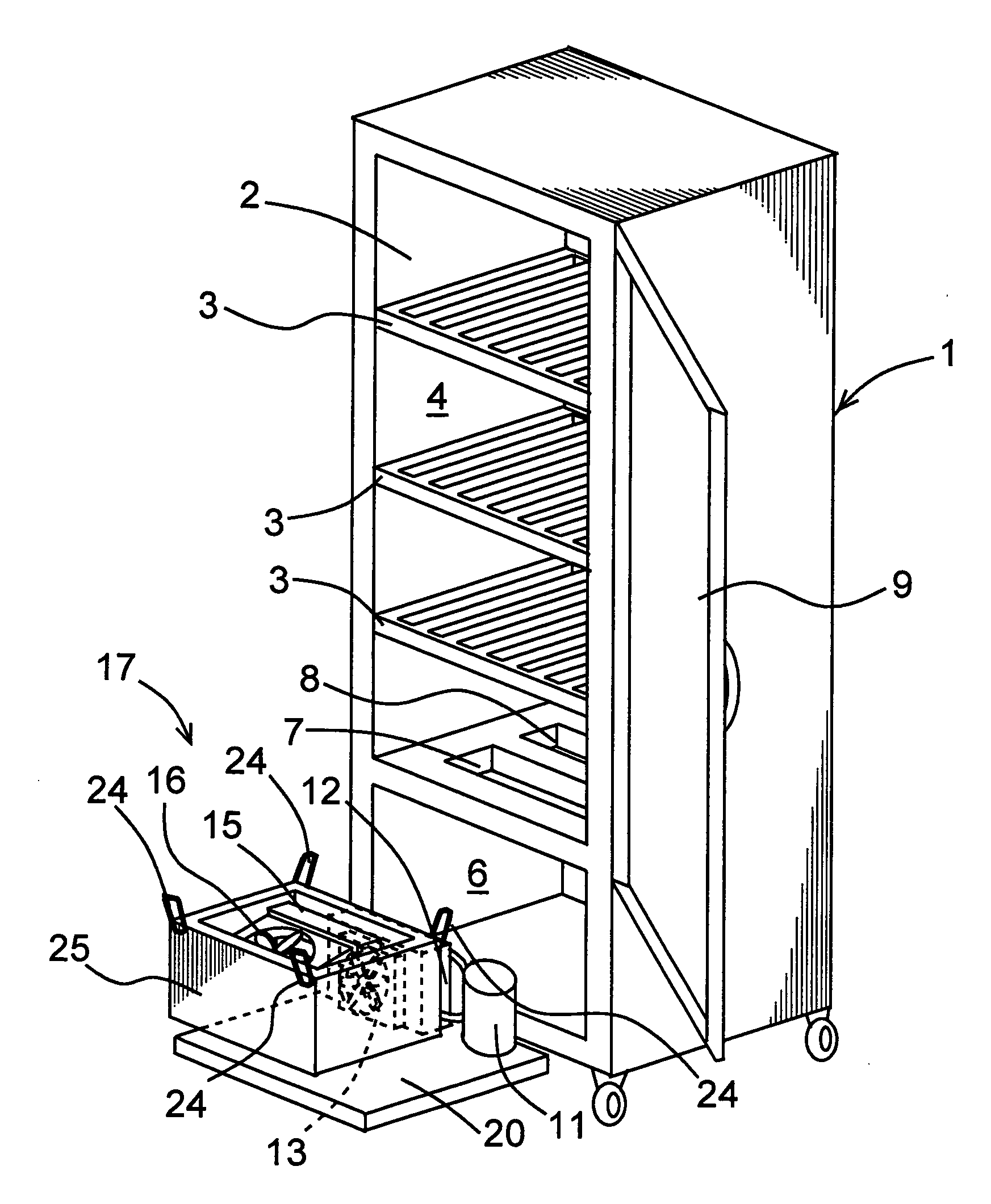
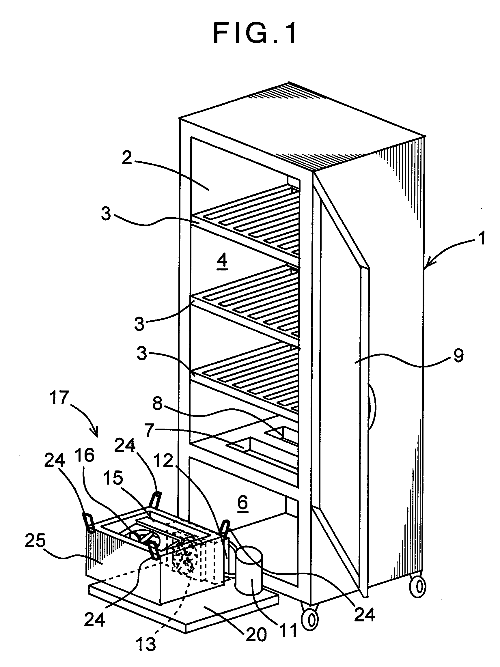
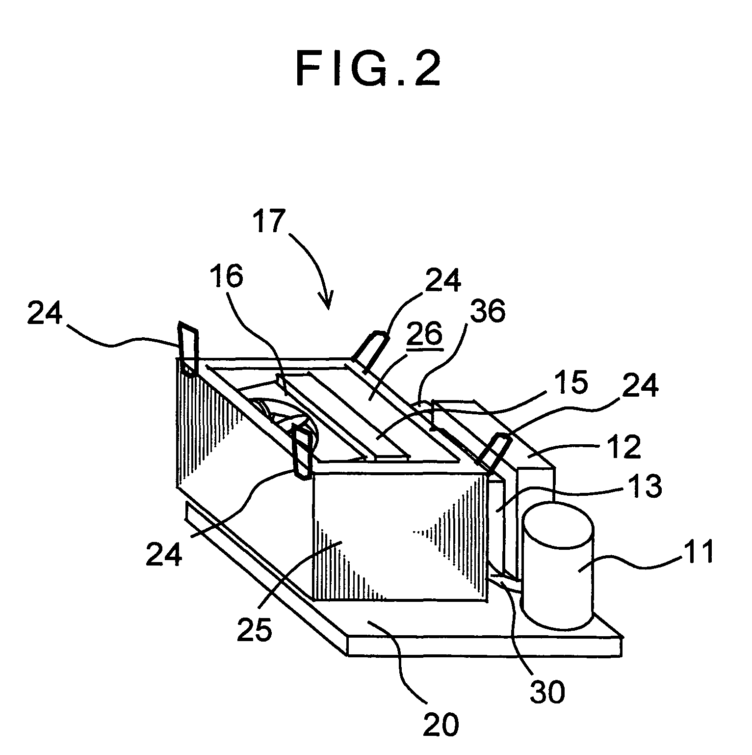
[0024]FIG. 1 shows a perspective view of a case where a refrigerating device of the present invention is adapted to a showcase as one embodiment of the present invention, and FIG. 2 shows an enlarged view of a refrigerating unit 17 of the showcase, respectively. It is to be noted that the refrigerating device of the present invention is usable in the showcase, an automatic dispenser, a refrigerator, a freezer and the like.

[0025]In FIG. 1, reference numeral 1 denotes a main body of the showcase, and this main body 1 is constituted of a rectangular insulating box member 2 which opens in a front surface. A plurality of stages (three stages in the embodiment) of shelves 3 . . . are built in the insulating box member 2, and a space on each shelf is constituted as a storage chamber 4 as a space to be cooled. The opening in the front surface is openably closed by a door 9 rot...


PUM


Abstract

An object is to improve an assembly operability while enhancing disconnecting and connecting properties between a main body and a refrigerating unit of a refrigerating device, and there is disclosed a refrigerating device (showcase) which is provided with a refrigerating unit including a refrigerant circuit constituted of a compressor, a radiator as a high-pressure-side heat exchanger, an evaporator as a low-pressure-side heat exchanger and the like and which supplies, by a blower, cold air subjected to heat exchange with the evaporator to a storage chamber as a space to be cooled constituted in a main body by a blower to cool the chamber, wherein a mechanical chamber is constituted under a bottom surface of the main body, the compressor and the radiator are installed on a unit base on the bottom surface of the mechanical chamber, and a refrigerating box in which the evaporator and the blower are stored is attached to the bottom surface of the main body via hooks so as to communicate with the storage chamber.

Description

BACKGROUND OF THE INVENTION[0001]The present invention relates to a refrigerating device provided with a refrigerating unit in which a refrigerant circuit is constituted of a compressor, a high-pressure-side heat exchanger, a low-pressure-side heat exchanger and the like.[0002]In this type of conventional refrigerating device, for example, a showcase installed in a shop, a refrigerant circuit is constituted of a compressor, a radiator as a high-pressure-side heat exchanger, pressure reducing means, an evaporator as a low-pressure-side heat exchanger and the like. Moreover, a refrigerant gas compressed by the compressor at high temperature and pressure is discharged to the radiator. After heat is discharged from the refrigerant gas by radiation, the pressure is reduced by the pressure reducing means, and the gas is supplied to the evaporator. The refrigerant evaporates there, exchanges heat with an surrounding area, and is cooled at this time. The cooled air (cold air) is fed, by a b...

Claims


Application Information

Patent Timeline
Patent Type & Authority Patents(United States)
IPC IPC(8): A47F3/04F25D19/00
CPCF25D19/00F25D23/006F25D11/00F25D23/00
Inventor YAMASAKI, HARUHISAYAMANAKA, MASAJI
Owner SANYO ELECTRIC CO LTD
Learn More