Extra-discal intervertebral stabilization device

Inactive Publication Date: 2013-04-23
SPINEWAY
View PDF9 Cites 6 Cited by
  • Summary
  • Abstract
  • Description
  • Claims
  • Application Information

AI Technical Summary

Benefits of technology

[0025]According to another characteristic, the body has a

Problems solved by technology

The result is a rigid assembly generating stresses and strains on the implants with the risks of screws breaking or loosening.
The link obtained is not sufficiently rigid and does not allow limitation of movement, particularly in extension.
Because of this there is excessive demand on the facet

Method used


Image

  • Extra-discal intervertebral stabilization device
  • Extra-discal intervertebral stabilization device
  • Extra-discal intervertebral stabilization device

Examples


Embodiment Construction

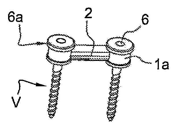
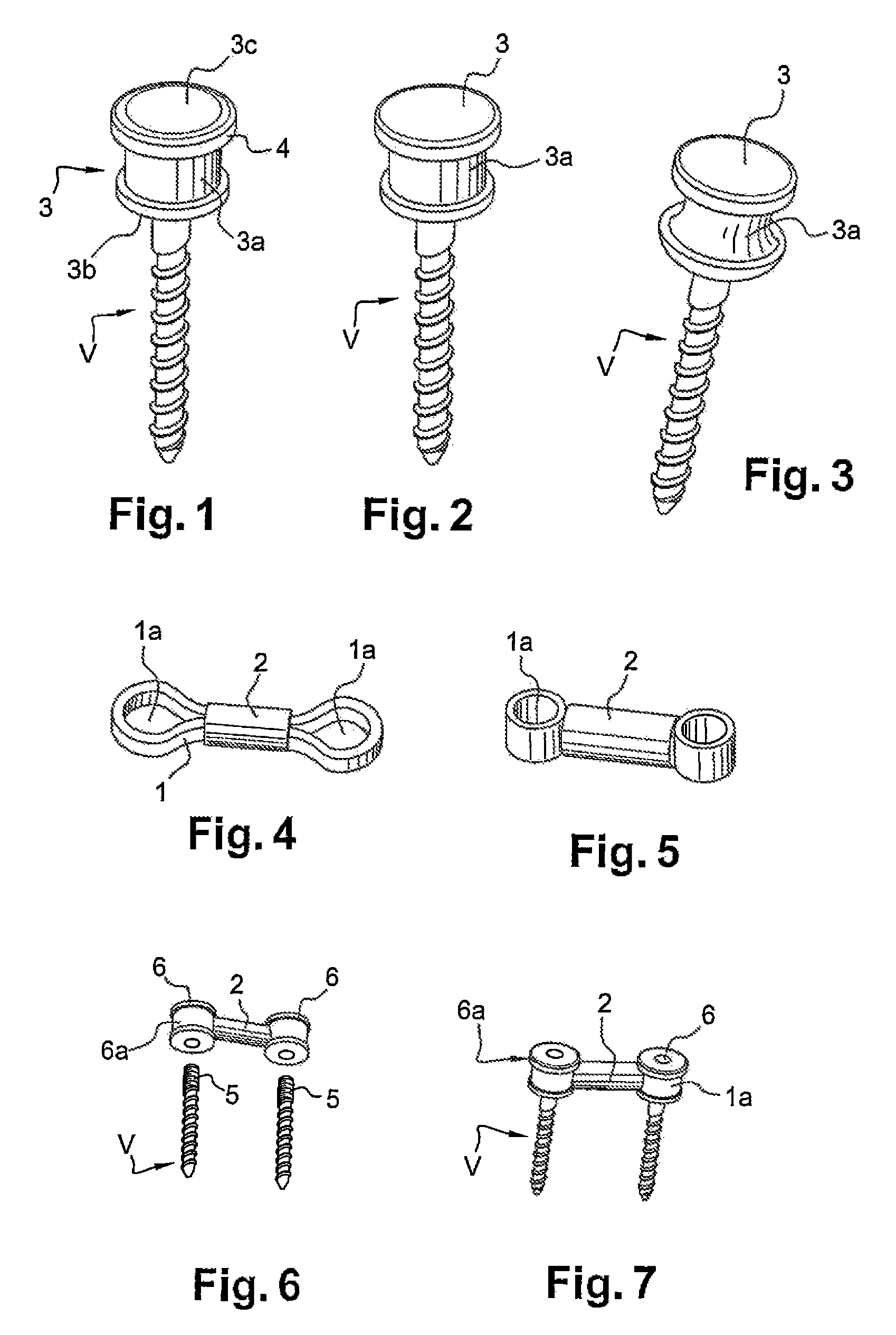
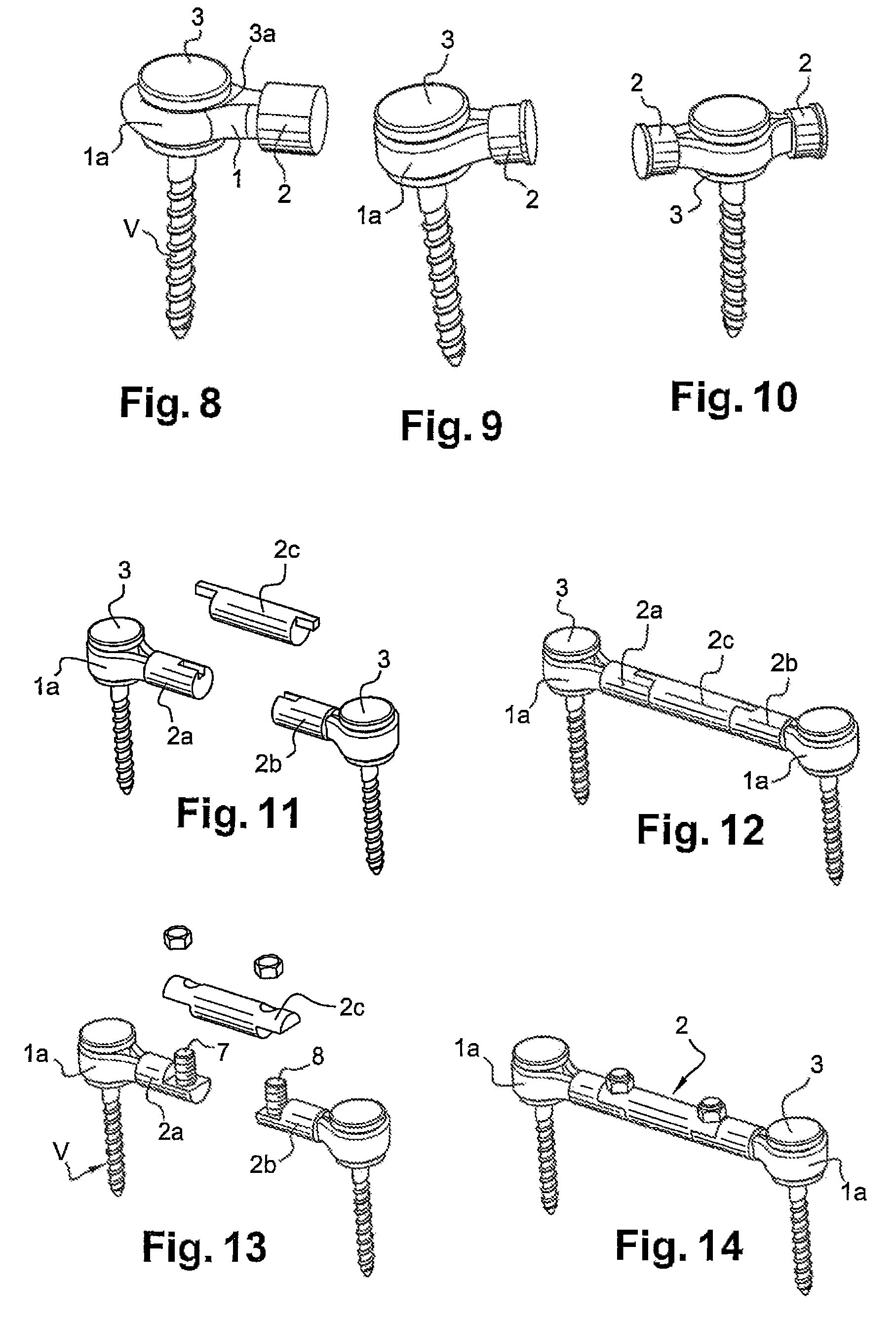
[0034]The intervertebral extra-discal stabilization device consists of at least two pedicle screws (V) cooperating with at least two different vertebrae. The screws (V) are linked by a linkage assembly composed of a flexible element (1), particularly in the form of a ligament, combined with a rigid part (2). The rigid part (2) is connected at each end to the heads of the screws (V) by the flexible element (1) forming a loop at each end (1a). The play between the screw head considered and the ligament (1) is so determined as to create reduced play suitable for allowing a limited range of movement in the sagittal, horizontal and frontal planes.

[0035]The movements permitted occur around the axis of the head of the pedicle screw (3). The ligament (1) avoids stresses being propagated in the screw and the rigid part (2). As a result of this there is better distribution of effort between the linking assembly and the vertebral bodies of the level operated. As concentration of stresses on th...


PUM


Abstract

An extra-discal device for intervertebral stabilization includes at least one rigid part connected to pedicle screws by an element. This rigid part comprises a cylindrical body, each end of which is firmly attached to the element which is flexible and deformable so as to be linked to a part of a corresponding pedicle screw with reduced play to obtain a limited range of multidirectional movement in the sagittal, horizontal and frontal planes, while limiting translational movement to the axis of the screw.

Description

CROSS REFERENCE TO RELATED APPLICATIONS[0001]This application is a national stage filing under section 371 of International Application No. PCT / FR2010 / 051626, filed on Jul. 29, 2010, and published in French on Mar. 24, 2011, as WO 2011 / 012829 and claims priority of French application No. 0955374 filed on Jul. 31, 2009, the entire disclosure of these applications being hereby incorporated herein by reference.BACKGROUND ART[0002]The invention belongs to the technical sector of mechanisms for intervertebral stabilization.[0003]The aim is to link at least two adjacent vertebrae in a manner known per se, to provide spinal stabilization allowing a range of movement between the vertebrae concerned.[0004]Various technical solutions have been proposed to achieve this objective. For example, there is a system consisting of a ligament within a rigid tube arranged between two pedicle screws and attached to the said screws. This rigid tube is placed in compression between the two screws, consequ...

Claims


Application Information

Patent Timeline
IPC IPC(8): A61B17/70
CPCA61B17/7007A61B17/7011A61B17/7014A61B17/7031A61B17/7025A61B17/705
Inventor LE ROUX, STEPHANELAURITO, PHILIPPE
Owner SPINEWAY
Why Eureka
Try Eureka