Illumination device with electrical variable scattering element

a scattering element and illumination device technology, applied in semiconductor devices, lighting and heating apparatus, instruments, etc., can solve the problems of device light loss, device inability to provide lighting devices, device complexity, etc., to achieve a larger colour gamut, broader tuning, and the effect of colour point and/or correlated colour being even more easily tuned

Inactive Publication Date: 2013-04-23
SIGNIFY HLDG BV
View PDF24 Cites 6 Cited by
  • Summary
  • Abstract
  • Description
  • Claims
  • Application Information

AI Technical Summary

Benefits of technology

[0011]Advantageously, such device may allow the possibility of colour tuning and / or correlated colour temperature tuning of the illumination device light, since the electrically variable scattering element may be used to scatter back (i.e. in an upstream direction) part of the light (especially the LED light) back to the luminescent material, which may lead to further absorption and a relative increase of the luminescent material emission. In this way, the colour point and correlated colour temperature (CCT) may be varied as function of the scattering. This may advantageously lead to an illumination device that also allows dimming substantially along the black body locus, something that is for instance hardly possible with conventional low pressure luminescent lamps.
[0042]As mentioned above, the luminescent material layer may in embodiments or may in other embodiments not be comprised by part of the wall(s) of the light chamber. Those parts of the wall(s) (including bottom) not comprising the luminescent material layer(s) are preferably reflective, and may for instance comprise a reflective coating. For instance MCPET (microcellular polyethylene terephthalate) may be applied as reflective material. In this way, good mixing of the LED light and the luminescent material emission may be obtained.
[0052]In a further embodiment, the illumination device may comprise a plurality of electrically variable scattering elements. Such embodiment may especially be used in combination with a plurality of chambers and / or a plurality of luminescent material layers. In this way, the colour point and / or correlated colour can even more easily be tuned. Hence, in a specific embodiment, the illumination device may comprise a plurality of luminescent material layers. To even further allow tuning of the optical properties of the device light, two or more of the plurality of luminescent material layers may have different emission characteristics. Therefore, in a specific embodiment, a first luminescent material layer and a second luminescent material layer may emit luminescent material emissions having different colour points, and especially different correlated colour temperatures. As will be clear to the person skilled in the art, further luminescent material layers may be present, which may optionally all have different colour points, and especially different correlated colour temperatures. This may allow a larger colour gamut and / or a broader tuning along the BBL of the illumination device light. For the sake of simplicity, herein only embodiments with such first luminescent material layer and second luminescent material layer, etc., are further discussed.
[0053]Especially, a first electrically variable scattering element is arranged downstream of the first luminescent material layer, and a second electrically variable scattering element is arranged downstream of the second luminescent material layer. Likewise, further electrically variable scattering elements arranged downstream of the further luminescent material layer, respectively, may be comprised by the illumination device. Especially, each electrically variable scattering element is arranged to be able to scatter, depending upon the set scattering, part of the light, especially the LED light, back to the respective luminescent material layer (in the chamber), thereby allowing further conversion of LED light into luminescent material emission, respectively.

Problems solved by technology

Disadvantages of prior art systems to tune the optical properties may be the use of relatively instable organic dyes, the complexity of the devices or the loss of device light the optical switches.
Further, such devices may for instance not easily be used to provide a lighting device able to tune the correlated colour temperature of the device light.
However this leads to incomplete use of the installed LEDs and consequently higher costs.
In addition, blue light conversion by a phosphor layer close to the LED die is not very efficient.

Method used


Image

  • Illumination device with electrical variable scattering element
  • Illumination device with electrical variable scattering element
  • Illumination device with electrical variable scattering element

Examples


Embodiment Construction

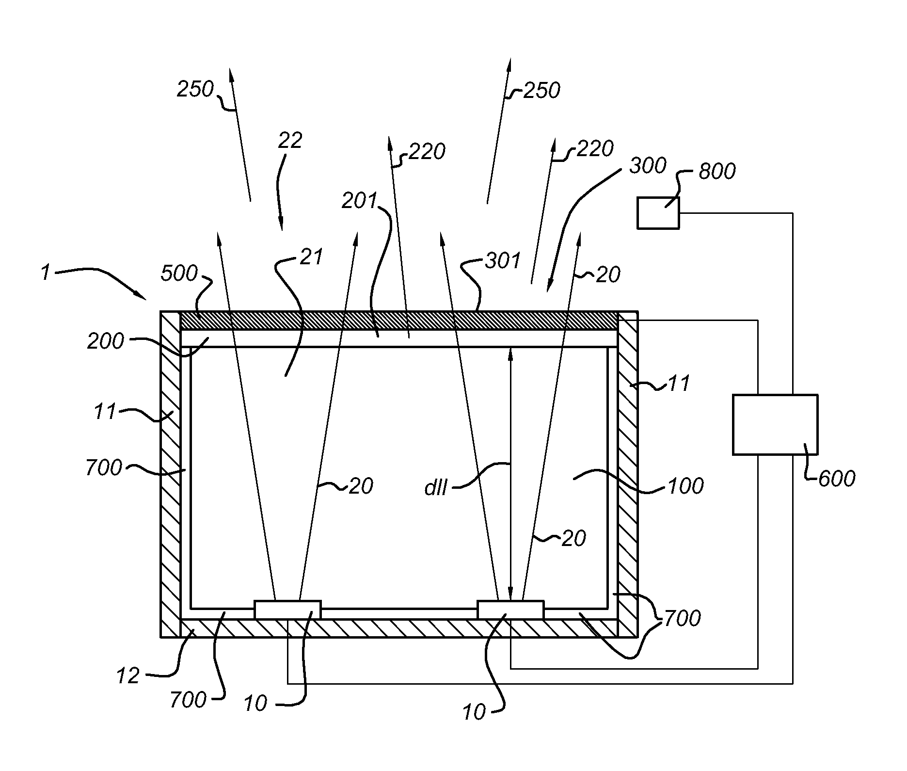
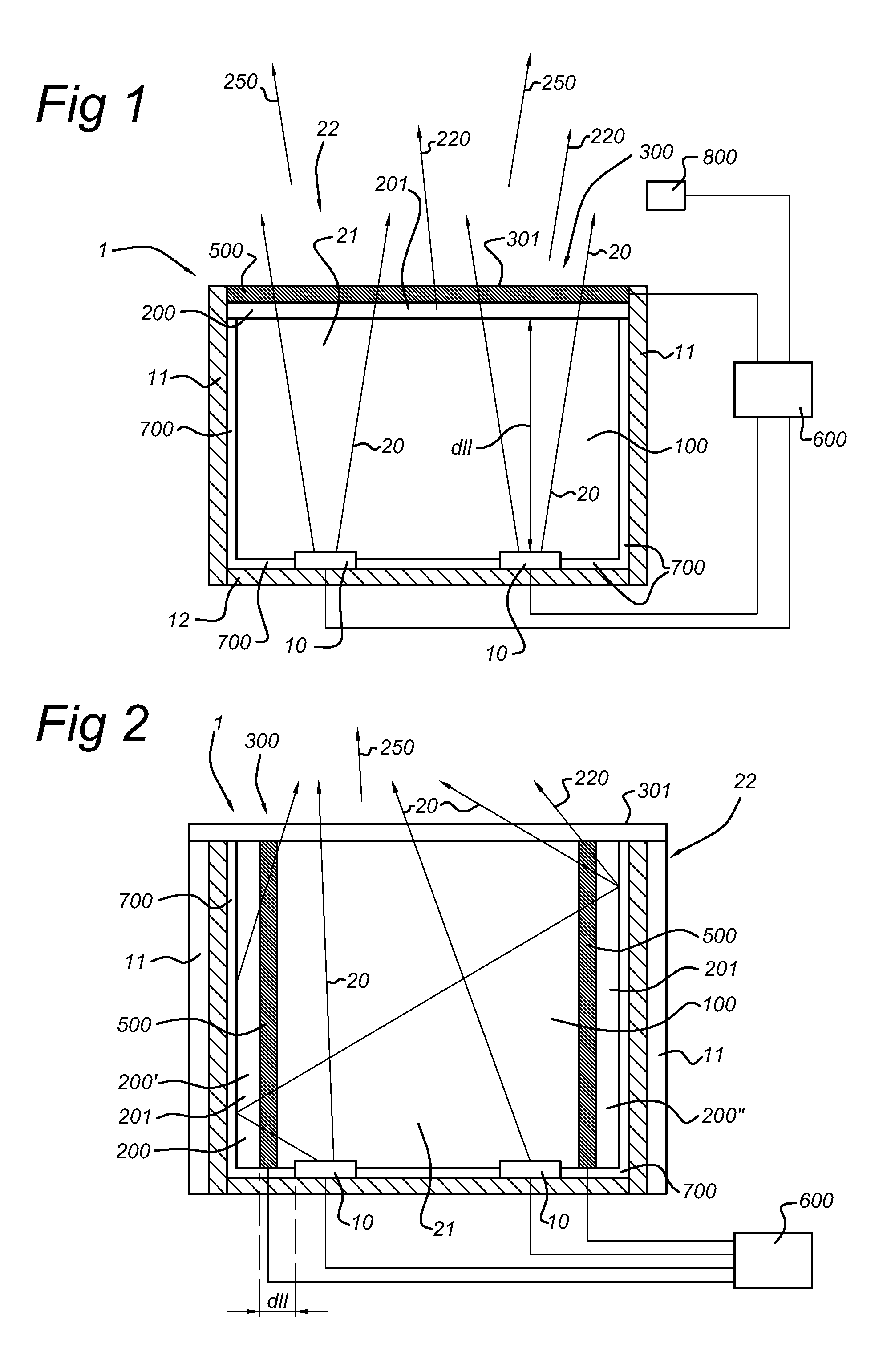
[0066]FIG. 1 schematically depicts an embodiment of an illumination device of the invention. The illumination device is indicated with reference 1; the illumination device light generated by the illumination device 1 in use is indicated with reference 250.

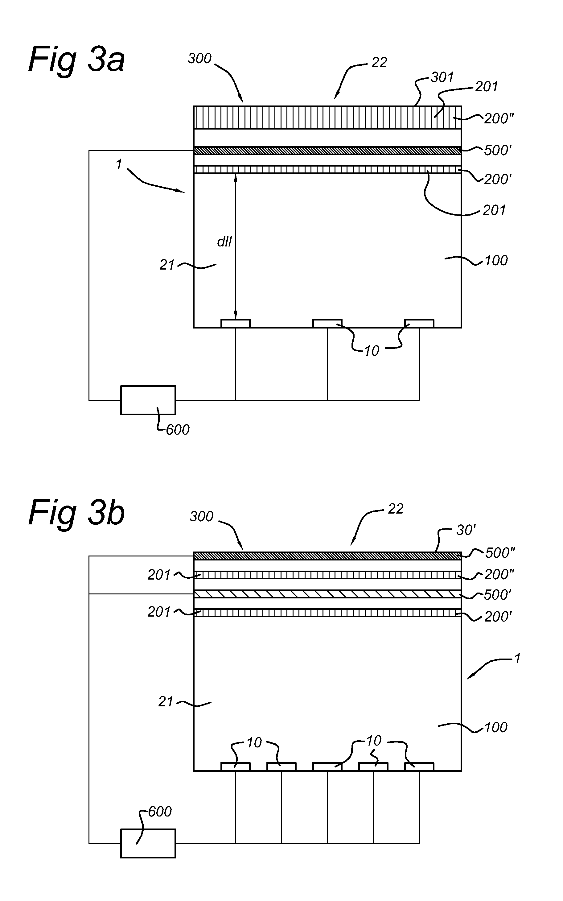
[0067]The illumination device 1 comprises a light chamber 100, an electrically variable scattering element 500, and a controller 600. The latter may be integrated into the illumination device 1 or may be arranged external from the device 1. The light chamber 100 is a cavity or chamber, which contains a light emitting diode 10, which in use emits LED light 20. The light chamber further comprises a luminescent material layer 200, which is arranged remote from the LED 10. The luminescent material layer comprise luminescent material 201. This luminescent material layer 200, or more especially the luminescent material 201, is able to absorb at least part of the LED light 20 and emit luminescent material emission, which is indicated with...


PUM

PropertyMeasurementUnit
correlated colour temperatureaaaaaaaaaa

Abstract

The invention provides an illumination device (1), arranged to provide illumination device light (250). The illumination device (1) comprising a light chamber (100), an electrically variable scattering element (500), and a controller (600). The light chamber (100) contains a light emitting diode (10) (LED) arranged to emit LED light (20); comprises a luminescent material layer (200) arranged remote from the LED (10) and arranged to absorb at least part of the LED light (20) and emit luminescent material emission (220); and comprises an exit face (301), through which one or more of the LED light (20) and the luminescent material emission (220) may escape to the exterior (22) of the light chamber (100) thereby providing illumination device light (250). The electrically variable scattering element (500) is arranged downstream of the luminescent material layer (200) and upstream of the exit face (301). The controller (600) is electrically connected to the electrically variable scattering element (500) and arranged to control the scattering of the electrically variable scattering element (500). Such device may allow the possibility of color tuning and / or correlated color temperature tuning of the illumination device light.

Description

FIELD OF THE INVENTION[0001]The invention relates to an illumination device comprising a chamber containing a light emitting diode (LED), and a luminescent material layer arranged remote from the LED. The invention further relates to the use of an electrical variable scattering element for use in such illumination device.BACKGROUND OF THE INVENTION[0002]Devices having a variable colour output are known in the art. US2007273265 for instance discloses a light emitting device with variable output colour. More specifically, this document describes a colour conversion cell which can be positioned in front of a light source in order to generate other colours or colour temperatures. Typically the light source is a light emitting diode (LED) which is power efficient but emits in a narrow and fixed spectra. The new colours are generated by photoluminescence in fluorescent dyes contained in the cell. The colour converting of the cell is electrically controllable, preferably by controlling the...

Claims


Application Information

Patent Timeline
Patent Type & Authority Patents(United States)
IPC IPC(8): G02F1/1333G02B26/00F21V9/16F21V9/40
CPCC09K11/0883C09K11/7734C09K11/7774C09K11/778F21V13/02F21V14/003F21V9/16G02F1/1334F21Y2101/02F21Y2115/10H01L33/58F21V9/38F21V13/08F21V9/32C09K11/77347C09K11/77348
Inventor BOONEKAMP, ERICANSEMS, JOHANNES P. M.VAN AS, MARCO
Owner SIGNIFY HLDG BV
Why Eureka
Try Eureka