X-ray tube target and method of repairing a damaged x-ray tube target

a technology of x-ray tube target and x-ray tube target, which is applied in the direction of x-ray tube target and convertor, material analysis using wave/particle radiation, instruments, etc., can solve the problems of high cost, limited recovery rate of damaged anode target, and possible damage to the target track of the anode target during use, so as to avoid high cost and significant savings

Active Publication Date: 2013-04-23
GENERAL ELECTRIC CO
View PDF32 Cites 3 Cited by
  • Summary
  • Abstract
  • Description
  • Claims
  • Application Information

AI Technical Summary

Problems solved by technology

Thus, for increased peak power applied, there are endurance and reliability issues with respect to the anode target.
Over time, the target track of the anode target and possibly a portion of underlying substrate material may be damaged during use.
Recovery rates of damaged anode targets are generally limited to targets with minimal track damage as candidates for reuse.
This is costly since it requires expensive deposition processes, such as plasma spray, chemical vapor deposition (CVD), physical vapor deposition (PVD), lazer engineered net shape (LENS), or electroplating (plating).

Method used


Image

  • X-ray tube target and method of repairing a damaged x-ray tube target
  • X-ray tube target and method of repairing a damaged x-ray tube target
  • X-ray tube target and method of repairing a damaged x-ray tube target

Examples


Embodiment Construction

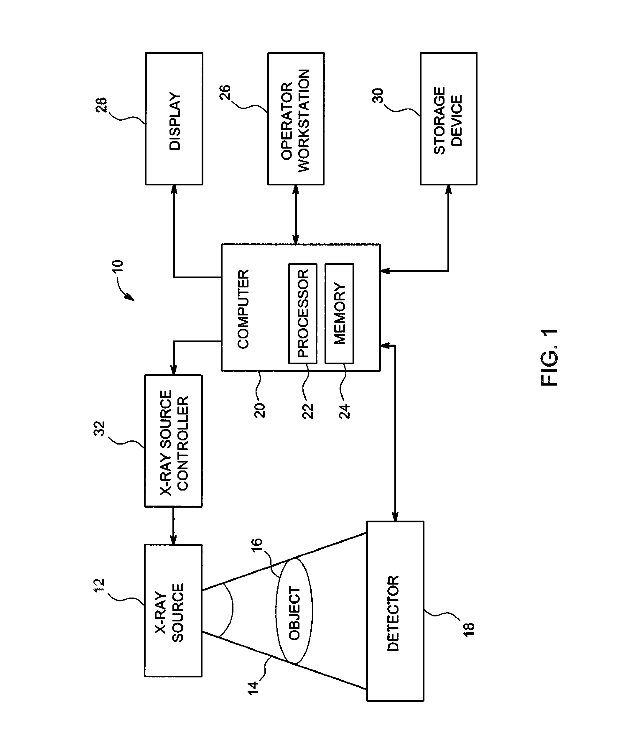
[0019]Referring now to the drawings, FIG. 1 illustrates a block diagram of an exemplary embodiment of an x-ray imaging system 10 designed both to acquire original image data and to process the image data for display and / or analysis. It will be appreciated by those skilled in the art that this disclosure is applicable to different types of x-ray imaging systems implementing an x-ray tube, such as radiography, mammography, and vascular imaging systems. Other imaging systems such as computed tomography (CT) systems and digital radiography (RAD) systems also benefit from this disclosure. The following discussion of x-ray imaging system 10 is merely an example of one such implementation and is not intended to be limiting in terms of modality.

[0020]As shown in FIG. 1, x-ray imaging system 10 includes an x-ray source 12 configured to project a beam of x-rays 14 through an object 16 and towards a detector 18. Object 16 may include human beings, animals, pieces of baggage, or other objects d...


PUM

PropertyMeasurementUnit
atomic numberaaaaaaaaaa
distanceaaaaaaaaaa
electric fieldaaaaaaaaaa

Abstract

An x-ray tube target and method of repairing a damaged x-ray tube target. The x-ray tube target includes an original substrate and a portion of the original substrate that includes a new portion of a substrate and a new target track that is attached to a void in the original substrate. The method includes removal and replacement of damaged materials on used anode targets of x-ray tubes, thereby enabling recovery of used anode targets without the use of expensive and time consuming layer deposition methods. The method also avoids the high costs and long development cycles associated with known repair and refabrication methods for anode targets of x-ray tubes.

Description

CROSS-REFERENCE TO RELATED APPLICATIONS[0001]This application is a continuation-in-part of and claims priority to U.S. patent application Ser. No. 11 / 737,932, filed on Apr. 20, 2007, the disclosure of which is incorporated herein by reference.BACKGROUND OF THE INVENTION[0002]This disclosure relates generally to x-ray generation systems, and more particularly to an x-ray tube target and a method of repairing a damaged x-ray tube target for x-ray generation.[0003]X-ray tubes generally include a cathode assembly and an anode assembly disposed within at least one vacuum vessel or enclosure. The cathode assembly is positioned at some distance from the anode assembly, and a voltage difference is maintained therebetween in order to extract and accelerate electrons from the cathode assembly towards the anode assembly. This voltage differential generates an electric field gradient having a strength defined by the voltage differential between the anode assembly and cathode assembly divided by...

Claims


Application Information

Patent Timeline
Patent Type & Authority Patents(United States)
IPC IPC(8): H01J35/10H01J35/08
CPCH01J35/10H01J2235/083Y10T29/4973H01J2235/1225H01J2235/1204
Inventor STEINLAGE, GREGORY ALANHEBERT, MICHAEL SCOTT
Owner GENERAL ELECTRIC CO
Why Eureka
Try Eureka