Power tool housing

a tool and tool body technology, applied in the field of power tools, can solve the problems of affecting the health of users, affecting the accuracy of tool biting, and difficult for users to accurately direct tool biting, etc., and achieve the effect of increasing the damping effect of damping means and greater pressur

Active Publication Date: 2013-04-30
BLACK & DECKER INC
View PDF38 Cites 24 Cited by
  • Summary
  • Abstract
  • Description
  • Claims
  • Application Information

AI Technical Summary

Benefits of technology

[0017]By providing first and second engaging portions that engage each other at a surface which tapers towards the working member of the tool, this provides the advantage that the transmission mechanism is guided into alignment with the housing when the first and second engaging portions come together, such that a user is assisted in aligning the tool bit of the power tool as the transmission mechanism is guided to align with the longitudinal axis of the tool bit. Also, as the first and second portions move apart, due to greater pressure applied by a user in response to tougher working conditions, the size of a gap between these portions slowly increases thereby increasing the damping effect of the damping means.

Problems solved by technology

The vibration caused by the bit of the hammer drill impacting on a surface can be transmitted to the user, which can be detrimental to the health of the user.
The vibration-damped tool of U.S. Pat. No. 5,947,211 suffers from the drawback that it is difficult for the user to accurately direct the bit of the tool as the shoulders and stop members do not guide the carrier device relative to the machine housing during operation.
The power tool of U.S. Pat. No. 6,776,245 suffers from the drawback that when the tool is in operation and the percussion mechanism is vibrating relative to the outer housing, it is difficult for the user to accurately direct the bit of the tool.
The handheld percussion power tool of US2004 / 0154813 suffers from the drawback that when the tool is in use and the percussion unit is moving relative to the housing, it is difficult for the user to accurately direct the bit of the tool due to the free-floating nature of the percussion unit.

Method used


Image

  • Power tool housing
  • Power tool housing
  • Power tool housing

Examples


second embodiment

[0079]A hammer drill of the invention is shown in FIGS. 9 and 10, with parts common to the embodiment of FIGS. 3 to 8 denoted by like reference numerals but increased by 100.

[0080]Crank pin 154 is of the same construction as the embodiment of FIGS. 3 to 8. However, in the embodiment of FIGS. 9 and 10 the collar member 176 is a coil spring. A washer 178 is provided between the collar coil spring 176 and the cylindrical bearing 156. The collar coil spring 176 has the further advantage of biasing the part-spherical bearing 170 of the crank pin 154 into engagement with the cup-shaped recess 172 of the crank plate 152 so that the part-spherical bearing is prevented from even partially moving out of engagement with the crank plate 152.

third embodiment

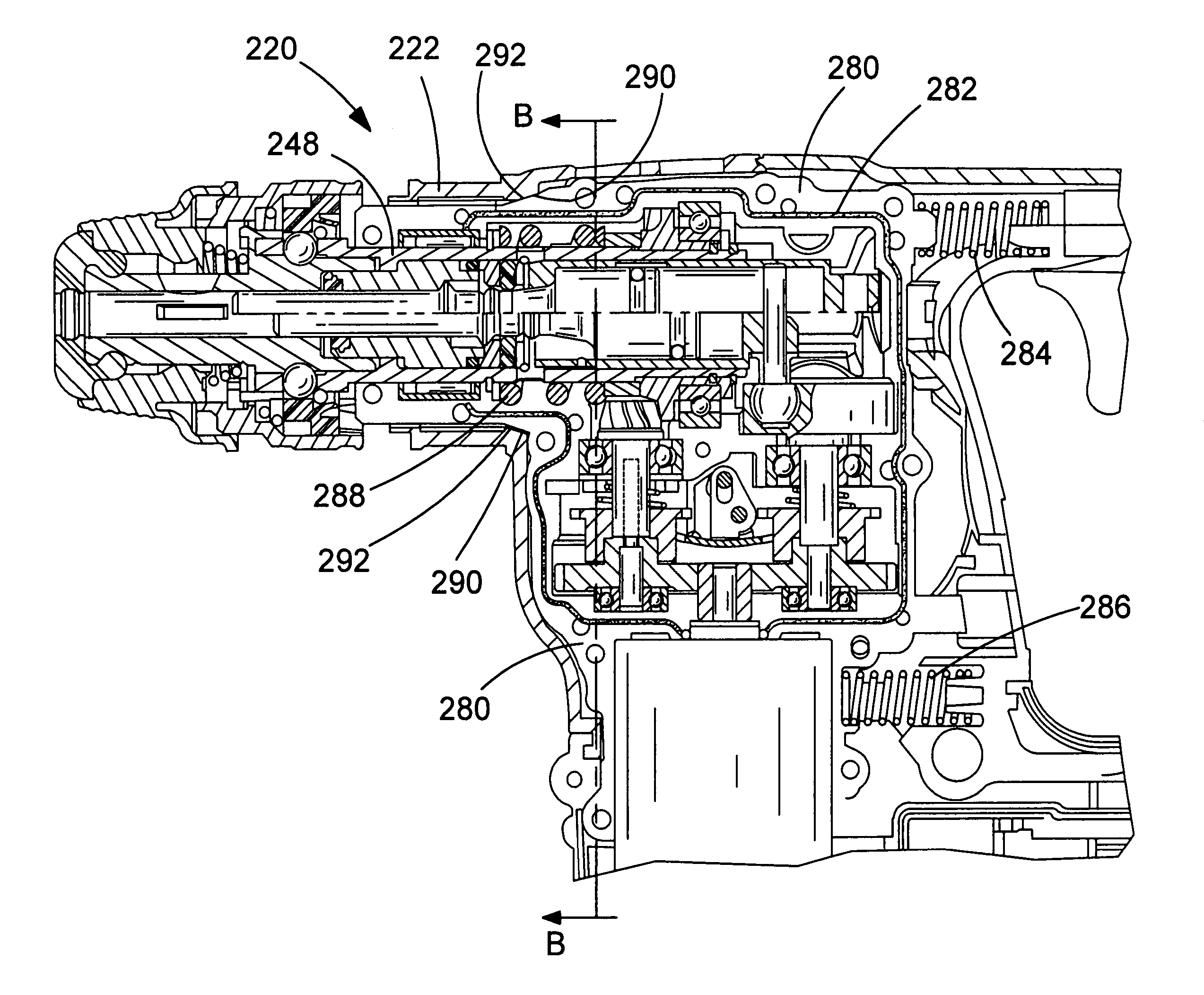
[0081]A hammer drill of the invention is shown in FIGS. 11 to 13, with parts common to the embodiment of FIGS. 3 to 8 denoted by like reference numerals but increased by 200.

[0082]The transmission housing 280 is formed from two clamshell halves of durable plastics or cast metal material. The two clamshell halves trap and compress an O-ring 282 therebetween. The transmission housing 280 is supported by first and second damping springs 284 and 286 at its rearward end. The transmission housing 280 is also mounted on parallel rails (not shown) disposed within the tool housing 222 such that the transmission housing 280 can slide a small distance relative to the tool housing 222 backwards and forwards in the direction of the longitudinal axis of the spindle 248.

[0083]The spring coefficients of damping springs 284 and 286 are chosen so that the transmission housing 280 slides to a point generally mid-way between its limits of forward and backward travel when the hammer drill is used in nor...

fourth embodiment

[0085]A hammer drill of the invention is shown in FIG. 14, with parts common to the embodiment of FIGS. 3 to 8 denoted by like reference numerals but increased by 300.

[0086]The hammer drill 320 has a tool housing 322. In this embodiment, the transmission housing 380 is formed from three housing portions. A generally L-shaped first housing portion 380a accommodates the transmission mechanism except for the first and second gears 340, 342 and the front end 348a of the spindle 348. The bottom end of the first housing portion 380a is mounted upon a second housing portion 380b such that a first O-ring 382a is trapped between the two portions to prevent the ingress of dust and dirt. The second housing portion 380b holds the lower parts of the transmission mechanism inside the first housing portion 380a and accommodates the first and second gears 340, 342. The second housing portion 380b has a motor output aperture 390 to allow the motor output shaft 336 access to the inside of the transmi...


PUM

PropertyMeasurementUnit
angleaaaaaaaaaa
axial movementaaaaaaaaaa
forceaaaaaaaaaa

Abstract

A hammer drill has a transmission housing 280 is formed from two clamshell halves of durable plastics or cast metal material. The transmission housing 280 is mounted on first and second damping springs 284 and 286 at its rearward end. The transmission housing 280 is also mounted on parallel rails (not shown) disposed within the tool housing 222 such that the transmission housing 280 can slide a small distance relative to the tool housing 222. The forward end of the transmission housing 280 has a generally part conical portion 290, which abuts a corresponding part conical portion 292 formed on the tool housing 222. The interface defined by conical portions 290 and 292 defines a stop against which the transmission housing 280 rests against the tool housing 222 in the inoperative condition of the hammer drill 220. When the hammer drill 220 is being used, a gap opens up between the conical surfaces 290 and 292 which helps to damp axial and lateral vibrations that would otherwise be transmitted from the tool bit (not shown) to the user. However, the gap is sufficiently small that the hammer drill 220 and the transmission housing 280 can still be adequately controlled by the user, and the part conical shape of the interface also assists in aligning the transmission housing 280 with the tool housing 222 in order to give a user greater control over the direction of the tool bit.

Description

FIELD OF THE INVENTION[0001]The present invention relates to a power tool, and relates particularly, but not exclusively, to a hammer drill.BACKGROUND OF THE INVENTION[0002]Hammer drills are power tools that have an electric motor that drives a hollow piston. A ram is disposed in the hollow piston and is caused to reciprocate under an air spring effect such that the ram strikes a beat piece in order to cause a hammer action.[0003]The vibration caused by the bit of the hammer drill impacting on a surface can be transmitted to the user, which can be detrimental to the health of the user. Consequently, several solutions to this problem have been proposed.[0004]U.S. Pat. No. 5,947,211 describes a vibration-damped hammer which has a machine housing that holds a drive motor and hammer mechanism to cause a hammering action. A carrier device comprising a frame structure forms a handle for a user, and is mounted by four leaf springs to the machine housing. The leaf springs act to absorb vibr...

Claims


Application Information

Patent Timeline
Patent Type & Authority Patents(United States)
IPC IPC(8): B25D17/00
CPCB25D16/00B25D17/24B25F5/006B25D2250/371
Inventor SOIKA, MARTINARICH, KLAUS-DIETERNEMETZ, UWE
Owner BLACK & DECKER INC
Why Eureka
Try Eureka