Method for configuring fieldbus stations

a fieldbus station and fieldbus technology, applied in the field of fieldbus stations, can solve the problem that the configuration or control program cannot be used precisely once, and achieve the effect of simplifying the work of a startup engineer

Active Publication Date: 2013-04-30
SIEMENS AG
View PDF5 Cites 16 Cited by
  • Summary
  • Abstract
  • Description
  • Claims
  • Application Information

AI Technical Summary

Benefits of technology

[0018]In accordance with the method of the invention, it is advantageous to operate the first fieldbus station as an automation device with a programmable logic controller and to store a program that controls a system in the first fieldbus station. Such fieldbus stations are called intelligent decentralized peripherals. I / O assemblies that can record and emit signals from the process are generally connected to such fieldbus stations, with the fieldbus station having its own CPU to assume control tasks.
[0021]In a further advantageous embodiment, during a system bootup of the first fieldbus station, a check is made therein to determine to which port of the coupling element it is connected using its first network port. If a coupling element, such as a switch, has a plurality of ports, then these ports are in a straightforward case numbered consecutively, such as Port-001, Port-002 or Port-003. After its system bootup, a user program in the first fieldbus station can request this consecutively numbered port name, such as Switch1.Port-001, through its first network port from the coupling element, i.e., from the switch, and by using this interrogation value the user program can accordingly continue to operate. This could be effected, for example, with a List Layer Discovery Protocol (LLDP).
[0024]Here, it is advantageous for the further system setups to be linked to the coupling element and for a unique station address and a unique station name to be produced for each fieldbus station after execution in accordance with the disclosed embodiments of the method, after which the system setups can commence their system operation trouble-free.

Problems solved by technology

However, the configuration or control program can only be used precisely once due to the addressing scheme.
Thus, the problem arises that the system startup engineer must have access to the configuration or the control program and must laboriously modify the configuration or the control program on site for each individual system setup.

Method used


Image

  • Method for configuring fieldbus stations
  • Method for configuring fieldbus stations
  • Method for configuring fieldbus stations

Examples


Embodiment Construction

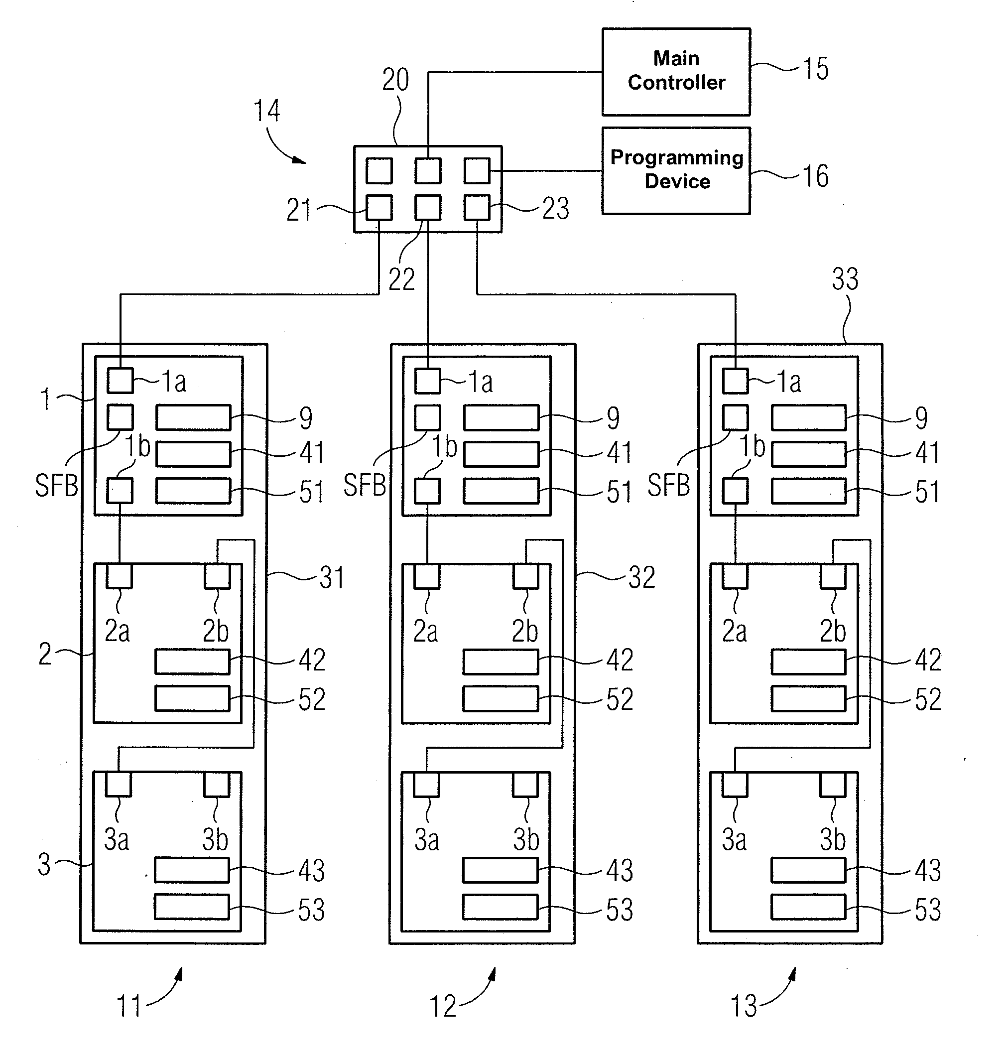
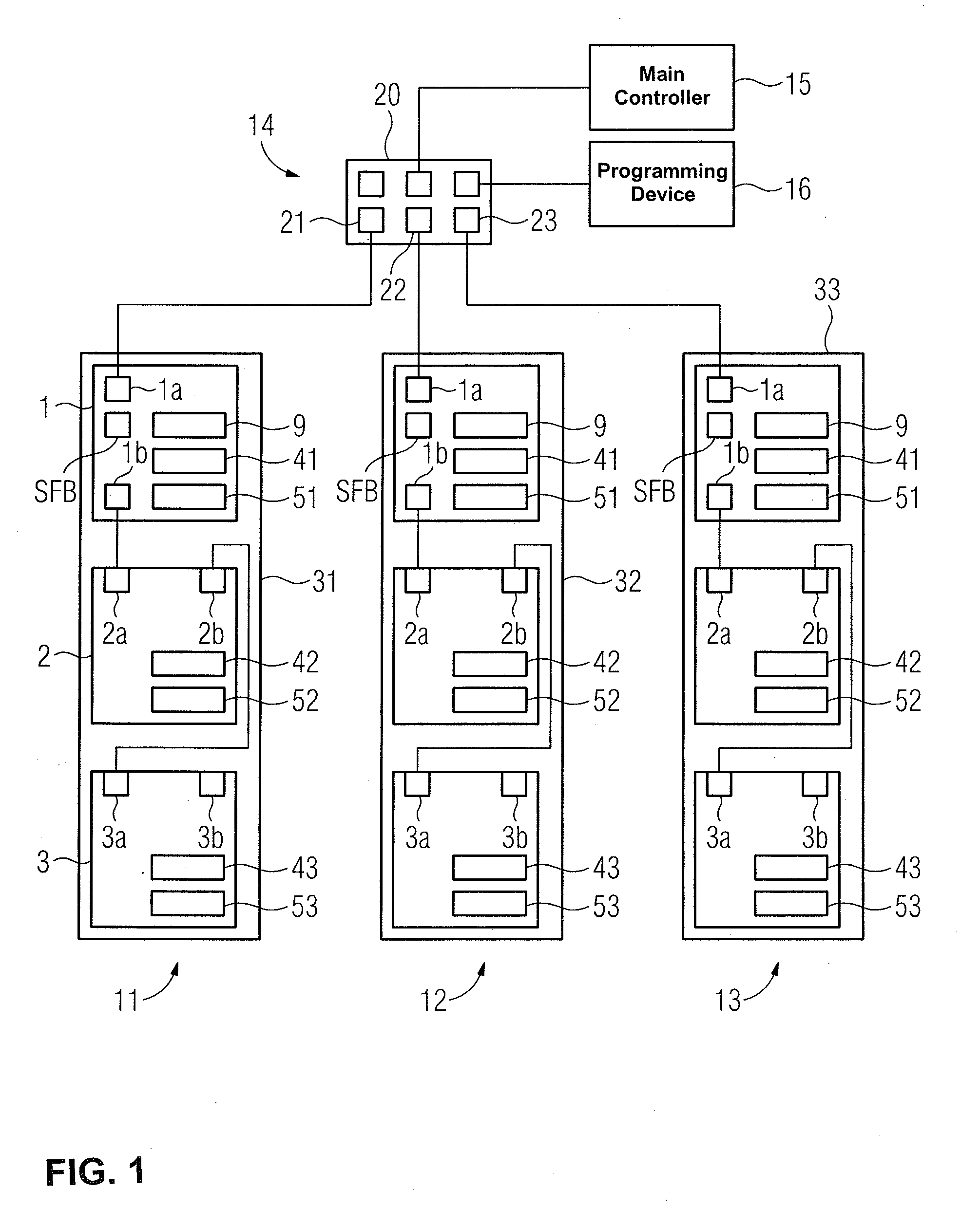
[0029]FIG. 1 shows an industrial system with a first system setup 31, a second system setup 32 and a third system setup 33 represented schematically. The system setups 31,32,33 are linked by a higher-level network 14 with a coupling element 20 to a main controller 15 and to a programming device 16. In addition to the ports for the main controller 15 and the programming device 16, the coupling element 20 has a first port 21 to which the first system setup 31 is connected by a fieldbus line, a second port 22 to which the second system setup 32 is connected by a fieldbus line, and a third port 23 to which the third system setup 33 is likewise connected by a fieldbus line. Here, the fieldbus lines are each configured as an Industrial Ethernet, PROFINET-IO.

[0030]The individual system setups 31,32,33, with their field devices 1,2,3, are each configured for a particular type of machine. Here, the first system setup 31 has, for example, a first fieldbus station 1, a second fieldbus station ...


PUM


Abstract

A method for configuring fieldbus stations, wherein station names and addresses for the fieldbus stations are executed by reading in a parameter over a first network port of a coupling element, which acts as a topology anchor so as to assign a unique addressing in a subnetwork, i.e., a unique name and a unique IP address, in a PROFINET-IO, such as a fieldbus based on Ethernet.

Description

BACKGROUND OF THE INVENTION[0001]1. Field of the Invention[0002]The invention relates to a fieldbus stations and, more particularly, to a method for configuring fieldbus stations in a subnetwork.[0003]2. Description of the Related Art[0004]Preferably, networks and fieldbus stations are used, for example, in process automation for the industrial automation of production systems. A known fieldbus is a PROFINET-IO bus, which is based on Ethernet technology. Such a PROFINET-IO bus requires a unique name and a unique IP address for each fieldbus station for addressing in its network, as well as in its subnetworks. If a system operator or planner has configured a system setup consisting of a plurality of fieldbus stations, and has written a control program for this system setup, this control program and the system setup are generally provided with unique addresses. This configuration or control program embodied in this way can be used in a fieldbus based on Ethernet technology. However, t...

Claims


Application Information

Patent Timeline
Patent Type & Authority Patents(United States)
IPC IPC(8): G06F3/00G06F13/00
CPCG05B19/41855H04L41/0806G05B2219/21042H04L2012/40221Y02P90/02
Inventor BIEHLER, GEORG
Owner SIEMENS AG
Why Eureka
Try Eureka