Elastic hydraulic accumulator/reservoir system

a hydraulic accumulator and hydraulic accumulator technology, applied in mechanical equipment, positive displacement engines, machines/engines, etc., can solve the problems of heat loss inefficiency, accumulator drawbacks, and difficulty in implementation of hydraulic regenerative braking (hrb), and achieve the effects of less space, less sliding friction, and lighter weigh

Active Publication Date: 2013-05-07
VANDERBILT UNIV
View PDF36 Cites 19 Cited by
  • Summary
  • Abstract
  • Description
  • Claims
  • Application Information

AI Technical Summary

Benefits of technology

[0007]The present invention discloses an accumulator / reservoir system for storing hydraulic energy. The disclosed system provides a compact, space saving design, in which the accumulator and the reservoir share space. That is, the low pressure reservoir of the hydraulic system is combined into the same space as the high pressure accumulator. Accordingly, the present invention requires less space and is lighter weight than traditional accumulator systems. A second feature of the system is that the fluid around the bladder accumulator lubricates the contact between the bladder and sides of the reservoir. This allows for decreased sliding friction as the bladder changes shape. The disclosed accumulator / reservoir system provides a method of storing strain energy in a fluid based system so that gas at a pressure greater than that of the fluid does not defuse into the fluid.
[0008]In certain embodiments, the accumulator system includes, a housing, wherein the housing defines a reservoir, a bladder attached to the housing, wherein the bladder is contained within the housing, a fluid, wherein the fluid is inside the bladder and in the reservoir surrounding the bladder so that movement of the bladder against the housing is lubricated. In certain embodiments, the fluid is a hydraulic fluid. In other embodiments, the system further includes a pump / motor in fluid communication with the bladder and reservoir. In still other embodiments, the system further includes a first fluid conduit attached to the housing and the pump / motor, a seal attached to the bladder, and a second fluid conduit attached to the pump / motor and the seal. In certain embodiments, the seal has a diameter greater than a diameter of the bladder so that removal of the seal allows for removal and replacement of the bladder.
[0010]Accordingly, one provision of the invention is to provide an accumulator / reservoir system having a compact design.

Problems solved by technology

One of the most pressing challenges in the design of an accumulator is the fabrication of a light weight and compact device that may be used in various industries.
Although a theoretically appealing concept, hydraulic regenerative braking (HRB) is difficult to implement due to some major inherent limitations and non-deal properties of conventional accumulators.
Such accumulators are subject to two serious drawbacks: 1) inefficiency due to heat losses, and 2) gas diffusion through the bladder into the hydraulic fluid.
The drawback of inefficiency via heat loss is addressable, but the gas diffusion issues gives rise to high maintenance costs associated with “bleeding” the gas out of the fluid often.
With regard to inefficiency, if the energy stored in the compressed gas of such an accumulator is not retrieved soon, the heat flow from the gas to its immediate surrounding results in much less energy being retrieved.
Since a vehicle remains immobile at a stop light for such a length of time or longer, this makes gas bladder and piston accumulators with a gas pre-charge not ideal for HRB applications.
This foam serves the purpose of absorbing the generated heat during gas compression that would otherwise be transferred to the walls of the gas enclosure, and ultimately lost.
Incorporation of elastomeric foam has shown how gas-charged accumulator efficiency can be improved, however, this modification still does not solve the other problems associated with existing accumulators.

Method used


Image

  • Elastic hydraulic accumulator/reservoir system
  • Elastic hydraulic accumulator/reservoir system
  • Elastic hydraulic accumulator/reservoir system

Examples


Embodiment Construction

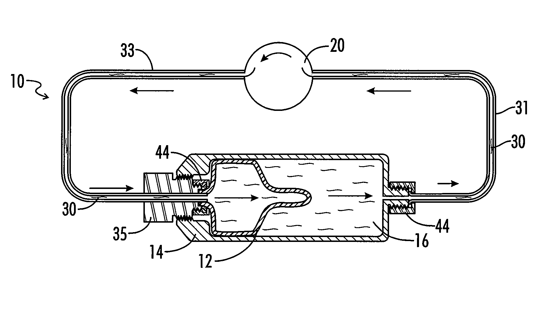
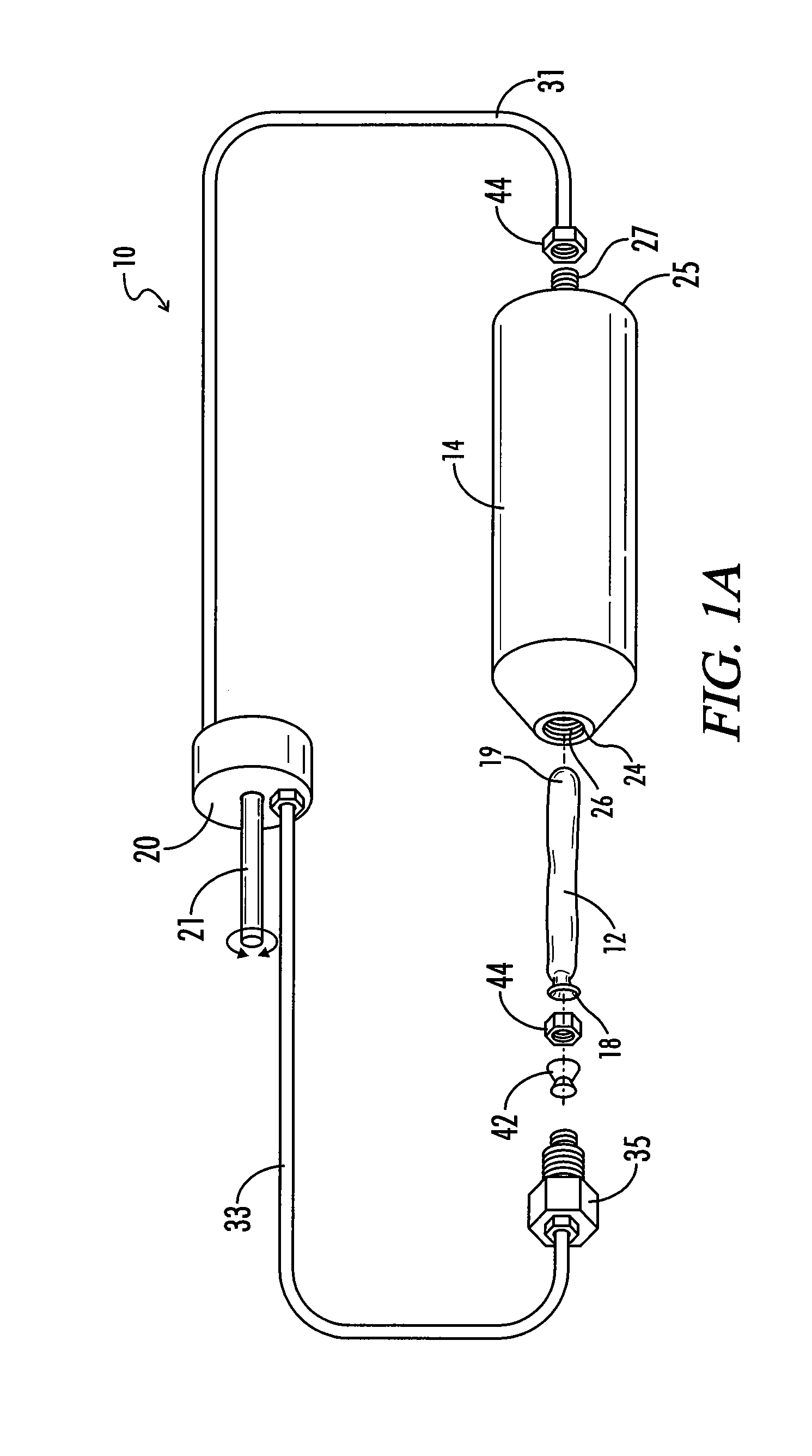
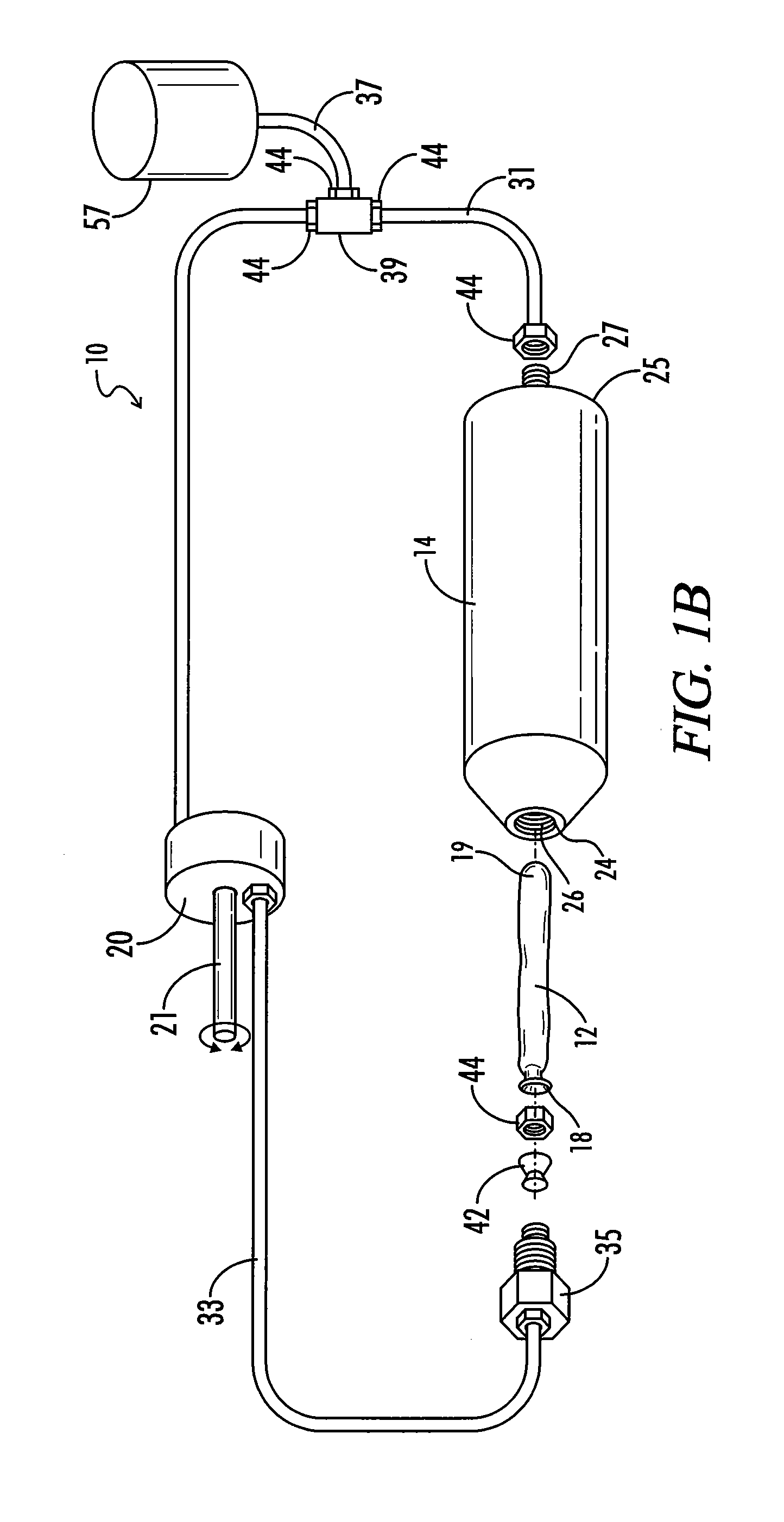
[0027]The present invention discloses a combined hydraulic accumulator and low pressure reservoir 16. This application discloses the way in which the low pressure reservoir 16 of a hydraulic system 10 may be combined into the same space as the high pressure accumulator if an elastic accumulator is used (where “high pressure accumulator” then refers to an elastic bladder 12 contained within the housing 14 which defines the reservoir 16. As shown and described herein, the invention is to utilize a high strain-energy density elastic accumulator (as opposed to a gas-charged or spring loaded piston accumulator) within a rigid shroud, also called a housing 14. As the inside of the elastic bladder 12 is filled (using a pump / motor 20, or other means), the volume around the bladder 12 decreases. Given that most elastic materials are incompressible and occupy appreciably the same volume regardless of their shape, the total combined volume of 1) the fluid 30, which may be hydraulic fluid, in t...


PUM


Abstract

The invention is a combination accumulator and reservoir which stores energy when the accumulator deforms from its original shape in response to the flow of a pressurized fluid from the reservoir. The stored energy is returned when the fluid flow is reversed and the accumulator discharges the fluid and returns to its original shape. At least one part of the novelty of the invention is that the accumulator and the fluid reservoir reside in the same housing such that the volume of each varies inversely. Accordingly, the invention is more compact and weighs less than conventional accumulators. Another feature of the invention is that fluid is located around the bladder accumulator to lubricate contact between the bladder and sides of the reservoir.

Description

STATEMENT REGARDING FEDERALLY SPONSORED RESEARCH OR DEVELOPMENT[0001]This invention was made, in part, with federal grant money under the National Science Foundation's Engineering Research Center for Compact and Efficient Fluid Power, grant number 0540834. The United States Government has certain rights in this invention.REFERENCE TO A MICROFICHE APPENDIX[0002]Not applicableBACKGROUND OF THE INVENTION[0003]One of the most pressing challenges in the design of an accumulator is the fabrication of a light weight and compact device that may be used in various industries. Hydraulic accumulators are energy storage devices commonly used to provide supplementary fluid power and absorb shock. One particularly interesting recent application of these devices is regenerative braking. Although a theoretically appealing concept, hydraulic regenerative braking (HRB) is difficult to implement due to some major inherent limitations and non-deal properties of conventional accumulators.[0004]Gas bladd...

Claims


Application Information

Patent Timeline
Patent Type & Authority Patents(United States)
IPC IPC(8): F16L55/04
CPCF15B1/04F15B1/26F15B1/02F15B2201/22F15B2201/405Y02E60/15Y02E60/16
Inventor BARTH, ERIC J.PEDCHENKO, ALEXANDER V.
Owner VANDERBILT UNIV
Why Eureka
Try Eureka