
Shock-absorbing treadmill

a treadmill and shock absorption technology, applied in the field of exercise treadmills, can solve the problems of reducing the likelihood of impact-related injuries, specialized equipment such as treadmills, and running outdoors has certain drawbacks

Active Publication Date: 2013-05-07
DH2PM2 LLC
View PDF26 Cites 39 Cited by
  • Summary
  • Abstract
  • Description
  • Claims
  • Application Information

AI Technical Summary

Benefits of technology

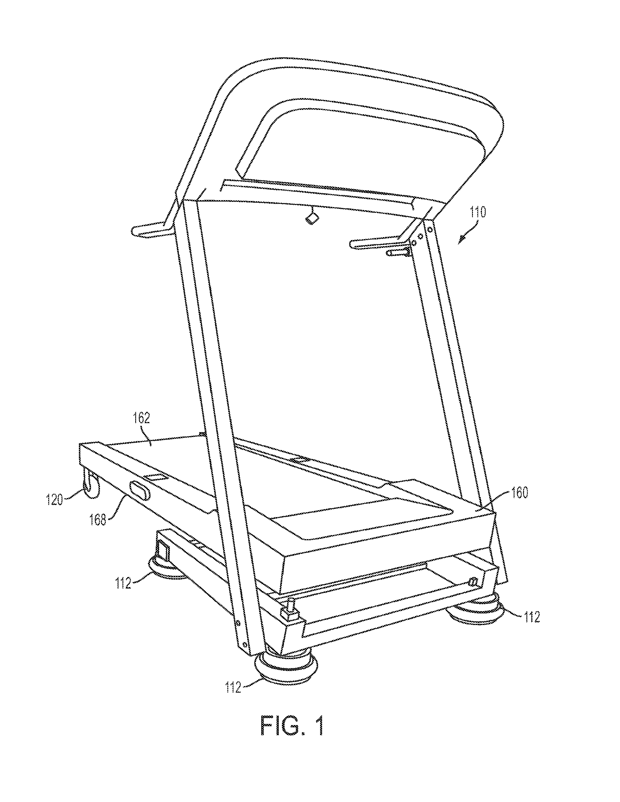
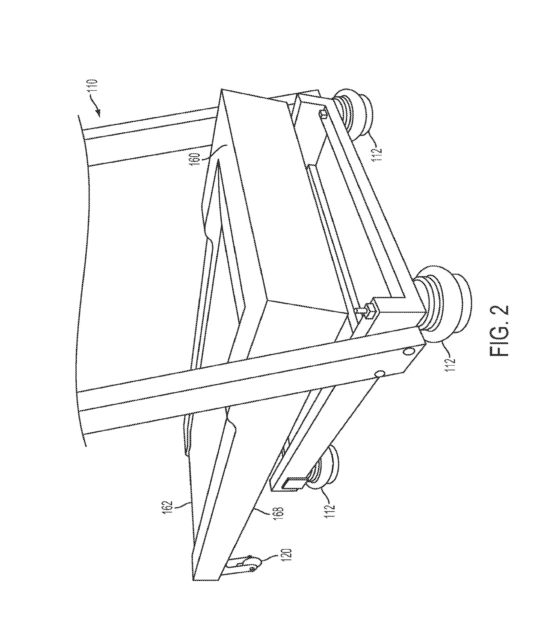
The present invention is about a treadmill that has air springs attached to it to absorb the shock on the body when running on the treadmill. There are two air springs located under the front of the treadmill and two more air springs located about one-third of the way from the front. The air springs can be attached using different means like glue, hook-and-loop fasteners, magnets, screws, nails, or other attachment means. In some cases, the treadmill may also have wheels at the back to allow for slight movement or travel as the front of the treadmill moves up and down with each stride taken by a person running on it.

Problems solved by technology

However, running outdoors has certain drawbacks that running on specialized equipment such as a treadmill does not.
Given that running as a cardiovascular exercise involves repeated impact over an extended period of time, reducing the impact on the body from each stride decreases the likelihood of impact-related injuries such as patellar tendonitis.

Method used


Image

  • Shock-absorbing treadmill
  • Shock-absorbing treadmill
  • Shock-absorbing treadmill

Examples


first embodiment

[0071]FIG. 3 is a bottom view of the front end 160 of the shock-absorbing treadmill 110 of the present invention. As can be seen, the air springs 112 are located on the underside 168 of the treadmill 110. The air springs 112 are located near the front end 160, with two air springs 112 directly underneath the front end 160 and another two air springs 112 located about one third of the way from the front end 160 of the treadmill 110.

[0072]FIG. 4 is a back view of the first embodiment of a shock-absorbing treadmill 110 of the present invention. As can be seen from this view, the treadmill 110 has wheels 120 rotatably connected to the underside 168 of the treadmill 110, on the back end 162, with one wheel 120 on the left side 164 and another wheel 120 on the right side 166 of the treadmill 110.

[0073]FIG. 5 is a perspective view of the lower portion of a second exemplary embodiment of the shock-absorbing treadmill 210 of the present invention, wherein the air springs 212 are inflatable a...

third embodiment

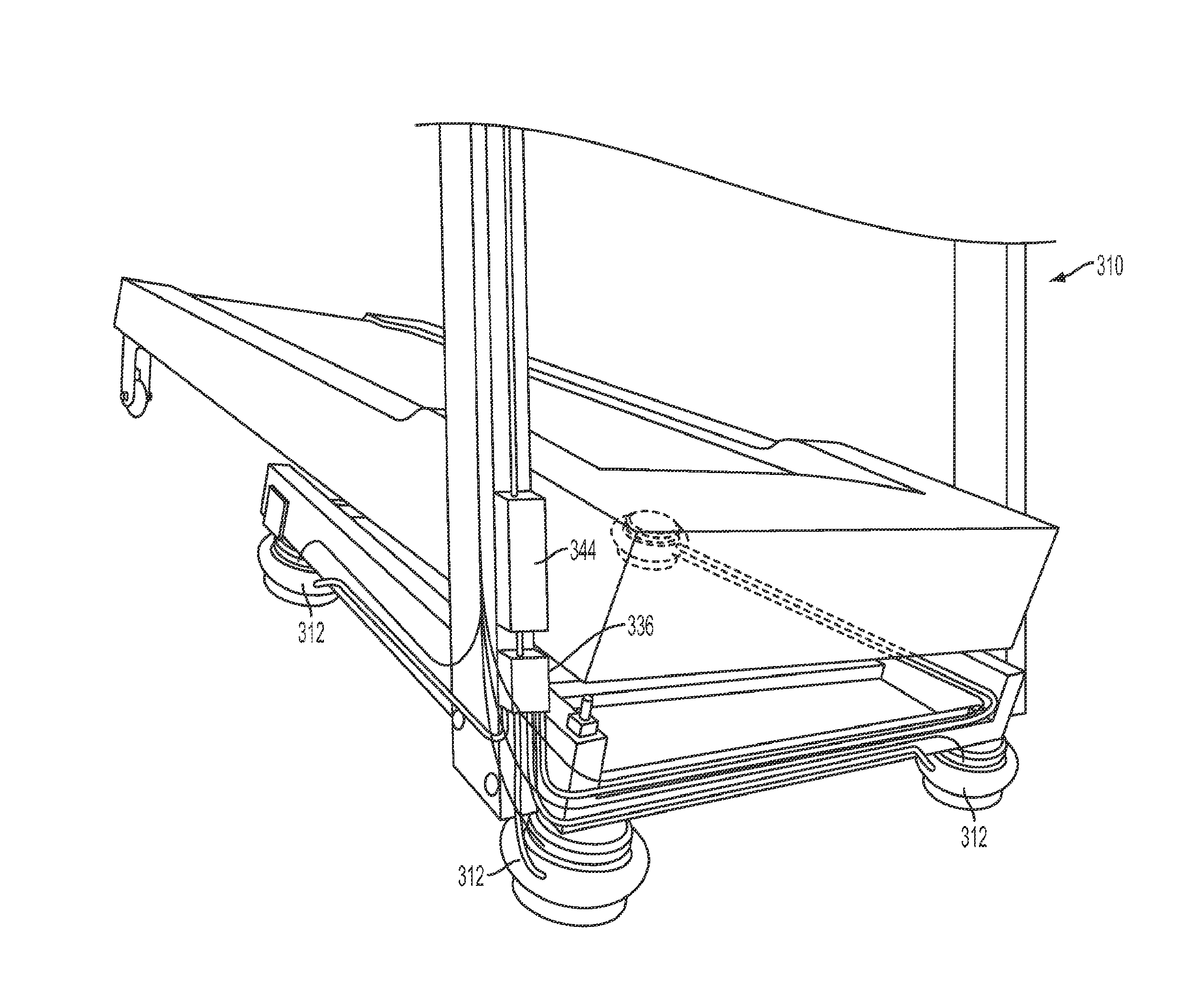
[0075]FIG. 7 is a front view of a dashboard 348 of a treadmill 310 according to the present invention, with an output device 350 adapted to provide information about the current pressure in air springs 312 (see FIG. 6), and optimal pressure settings for various weight ranges. The dashboard 348 also includes a control panel 352 for adjusting the pressure in the air springs 312. The control panel 352 includes an up arrow button 354, which, when pressed, causes an electrical signal to be sent to the air compressor 344, to deliver air to the air springs 312, thereby increasing the air pressure in each air spring 312. Pressing the down arrow button 356 causes an electrical signal to be sent to the air compressor 344 to release air from each air spring 312. It should be understood that in other embodiments, instead of up and down arrow buttons, the control panel may have a butterfly switch or other toggle for causing the air compressor to inflate or deflate each air spring. The pressure s...


PUM


Abstract

A treadmill having one or more air springs attached to the underside of the treadmill and one or more wheels on the underside of the treadmill near the back end of the treadmill, to provide increased shock-absorption over conventional treadmills. Other embodiments disclosed herein include treadmills with the above-discussed components as well as one or more air compressors, pressure sensors, and / or weight sensors for adjusting the level of pressure in the one or more air springs, based on the weight of a person using such a treadmill.

Description

TECHNICAL FIELD[0001]The present disclosed subject matter relates to exercise treadmills and more specifically to a shock absorbing frame for a treadmill.BACKGROUND ART[0002]Cardiovascular exercise, also known as cardiorespiratory exercise or aerobic exercise focuses on the human body's use of oxygen in metabolic processes and strengthening slow-twitch muscles. To stimulate these physiological processes, cardiovascular exercises are performed at moderate levels of intensity for extended periods of time, relative to anaerobic exercises which focus on building fast-twitch muscle. Cardiovascular exercise has been linked to many benefits including the prevention of heart disease and diabetes, rebuilding of lung tissue after quitting smoking, improved circulation, reduction of cholesterol and fat, more efficient use of oxygen, increased endurance, improved mental health, and a greater life span.[0003]Perhaps the oldest and most popular form of cardiovascular exercise is running. Scientis...

Claims


Application Information

Patent Timeline
Patent Type & Authority Patents(United States)
IPC IPC(8): A63B22/02
CPCA63B22/02A63B22/0285A63B2022/0221A63B2024/009A63B2220/52A63B2220/56A63B2225/62A63B22/0221
Inventor CLUM, GERALD M.HAZZOURI, DAVID
Owner DH2PM2 LLC
Learn More