
Refrigerant line electrical ground isolation device for data center cooling applications

a technology for data center cooling and electrical ground isolation, applied in the direction of electrical apparatus construction details, threaded fasteners, bolts, etc., can solve the problems of nonconductive lines being susceptible to refrigerant permeation, generating an enormous amount of heat, and preventing or inhibiting leakage (permeation). , to achieve the effect of minimizing charge buildup and preventing or inhibiting leakag

Inactive Publication Date: 2013-05-07
CALVARY APPLIED TECH
View PDF90 Cites 12 Cited by
  • Summary
  • Abstract
  • Description
  • Claims
  • Application Information

AI Technical Summary

Benefits of technology

The invention relates to an isolator component that prevents the leakage of refrigerant and the discharge of static electric charge in a refrigeration system. The isolator component is designed as a cylindrical tube with an inner wall that allows the refrigerant to pass through. It is made of a strong and durable material, such as HDPE, which can withstand extreme temperatures. The isolator component may be located between the pump and heat exchangers or at other suitable locations. Overall, the invention enhances the efficiency and safety of the refrigeration system.

Problems solved by technology

Some industries require concurrent operation of many electronic devices positioned in close proximity to each other which generates an enormous quantity of heat which must be constantly drawn away from the electronic devices.
One potential drawback of using electrically conductive metal lines to carry the refrigerant from the pump to a location close to the electronic devices is interference between the ground of the A / C powered refrigerant pump and the ground of the D / C powered electronic devices.
While one potential solution would be to use nonconductive lines such as PTFE or ETFE, for example, such nonconductive lines is susceptible to refrigerant permeation due to the molecular make-up of these non-conductive materials.
As stated above, while metal lines are preferred for carrying the refrigerant from the pump to the heat exchangers located in proximity to the electronic devices, since the metal lines are electrically conductive, the potential exists that the different electric grounding schemes of the A / C powered pump and D / C powered electronic devices may interfere with one another through these interconnecting, conductive metal lines.
Furthermore, the refrigerant itself is generally non-conductive and may develop a static electric charge as it flows through a non-conductive material such as the above plastics due to the triboelectric effect.

Method used


Image

  • Refrigerant line electrical ground isolation device for data center cooling applications
  • Refrigerant line electrical ground isolation device for data center cooling applications
  • Refrigerant line electrical ground isolation device for data center cooling applications

Examples


example 1

[0035]In normal operation, the insulating properties of the plastic or non-conducting material used to manufacture the isolator impede the bound charge on the inner wall from being conducted to ground at external locations along the isolator. Typically, the volume resistivity of the plastic materials used is on the order of 1011 ohm·m and higher, depending upon the material. The relative dielectric constant ∈I of the plastic is in the range of approximately 2.5 to 4.5, depending upon the material. For HDPE, for example, ∈I is 2.3. The electrical breakdown voltage (i.e. the dielectric strength) of the plastic material is in the range of 300-500 kV / inch, depending on the material. For HDPE, the dielectric strength is in the range 450-500 kV / inch.

[0036]If the isolator cylinder is assumed to have a uniform electrostatic charge per unit length σI on its inner surface the surrounding electric field EI in the radial region, with the radius r in the range of ri≦r≦ro=ri+tI, can be expressed ...


PUM

PropertyMeasurementUnit
volume resistivityaaaaaaaaaa
relative dielectric constant ∈Iaaaaaaaaaa

Abstract

An isolator to electrically isolate the A / C and D / C ground planes in a refrigerant network. When positioned along conductive refrigerant lines flowing with a dielectric refrigerant, the isolator is formed of a material which will prevent refrigerant permeation through its walls, and is further designed with dimensions that will prevent material breakdown and potentially damaging arcing due to triboelectric effect.

Description

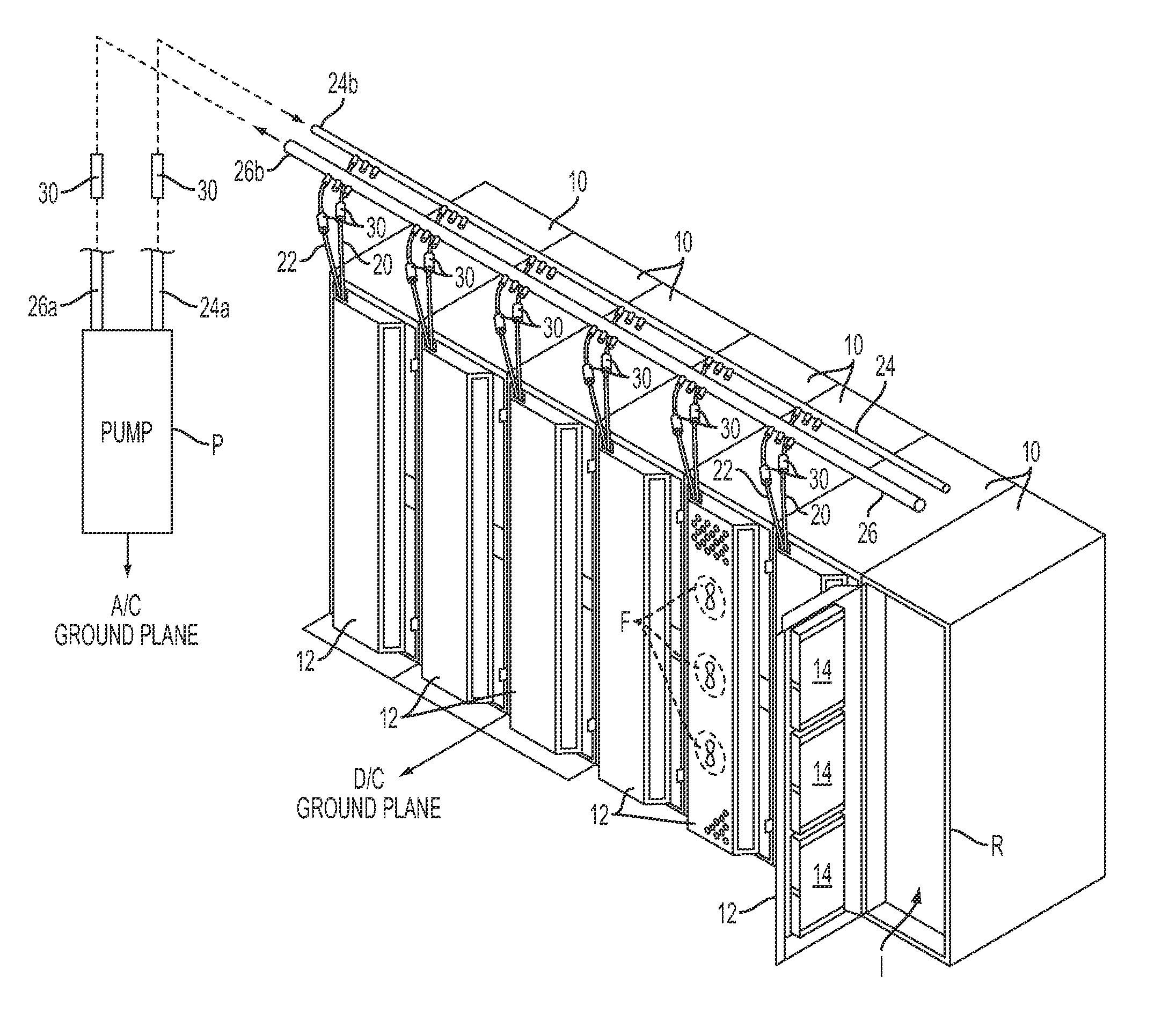
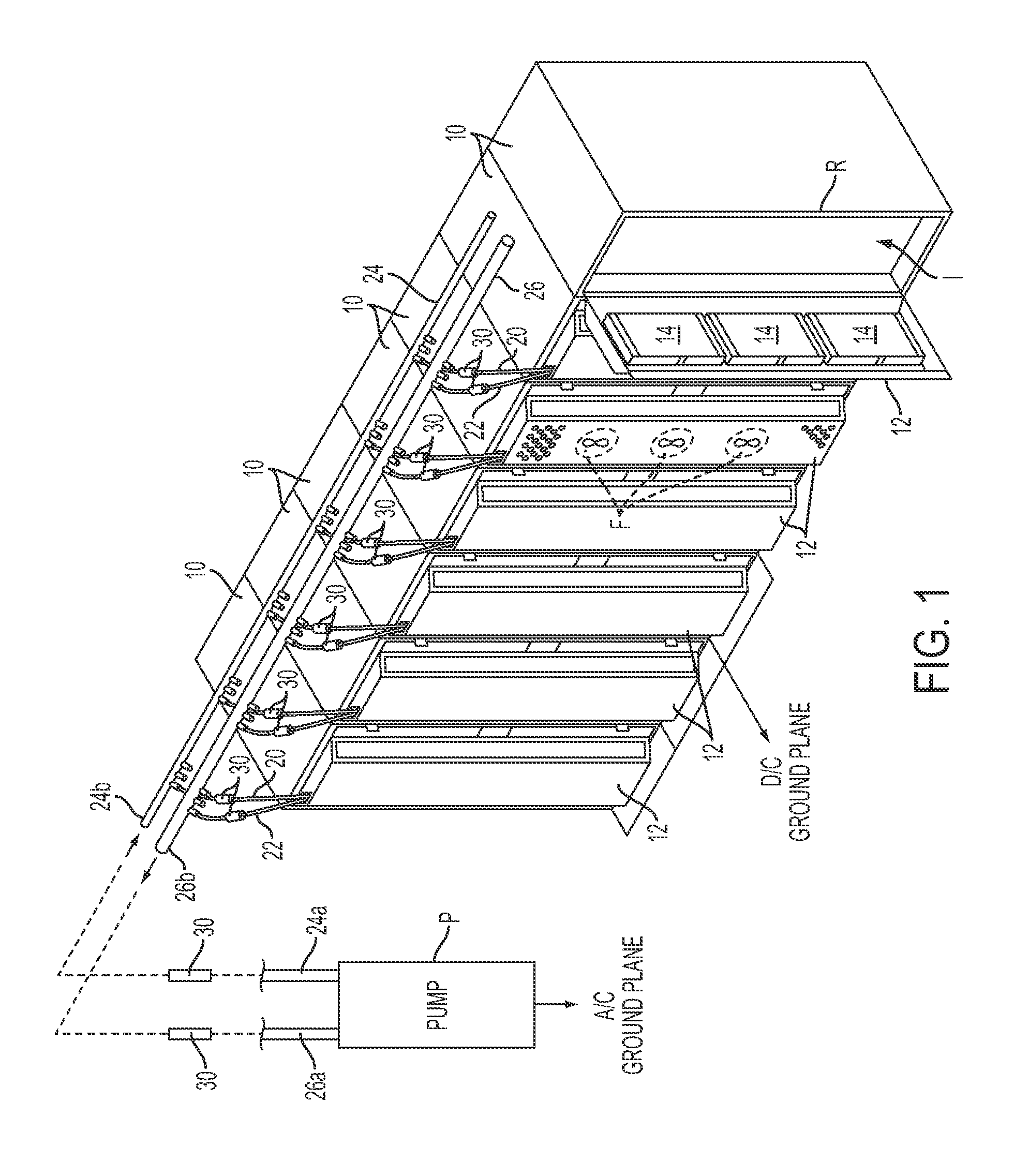
BACKGROUND OF THE INVENTION[0001]The present invention generally relates to electrical insulators, and more particularly relates to an electrical insulator (also referred to herein as an “isolator”) for electrically isolating different electrical ground systems by locating the isolator between and interconnecting separated lengths of electrically conductive refrigerant lines which extend between the ground systems and carry a liquid refrigerant therethrough for cooling electronic devices.[0002]Electronic equipment is known to generate heat which must be rejected from the device to prevent overheating and malfunction. Some industries require concurrent operation of many electronic devices positioned in close proximity to each other which generates an enormous quantity of heat which must be constantly drawn away from the electronic devices. The electronic devices (e.g. computer servers) are typically placed in electronic device frames or racks which are placed in repeating rows within...

Claims


Application Information

Patent Timeline
Patent Type & Authority Patents(United States)
IPC IPC(8): H01B17/14F16B33/00
CPCH05K7/20272H05K7/20781
Inventor SCOFIELD, WILLIAM H.BAUBE, SCOTT H.
Owner CALVARY APPLIED TECH
Learn More