

Radar system comprising overlapping transmitter and receiver antennas
a technology of overlapping transmitter and receiver antennas, applied in the field of radar systems, can solve problems such as misinterpretation of situations, and achieve the effect of improving angle determination
- Summary
- Abstract
- Description
- Claims
- Application Information
AI Technical Summary
Benefits of technology
Problems solved by technology
Method used
Image

Examples
embodiment 1
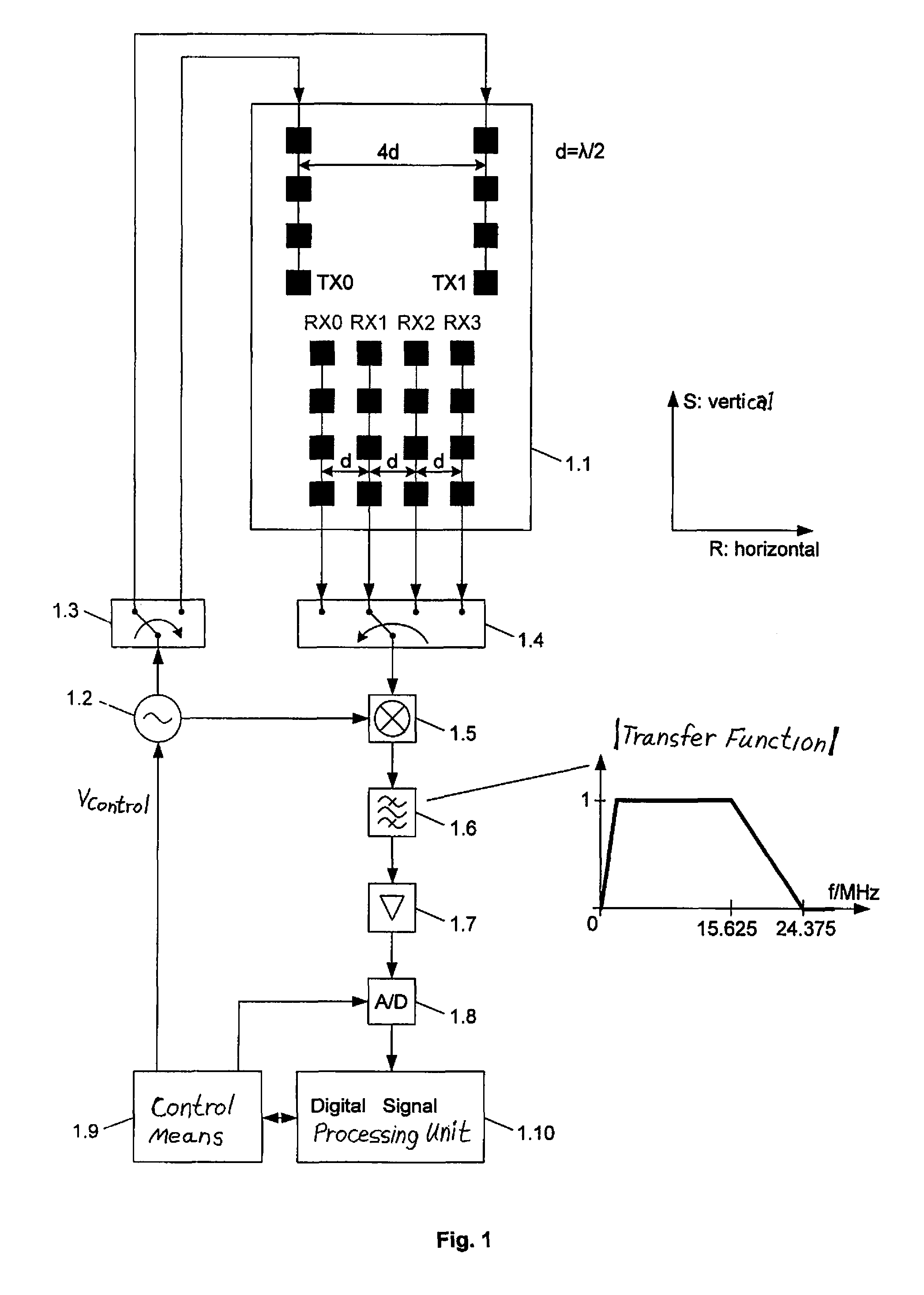
According to FIG. 1
[0057]At first, the exemplary embodiment of a radar system, which is roughly shown in FIG. 1 is considered. The radar system has 2 transmitter antennas TX0 and TX1 for emitting transmission signals and 4 receiver antennas RX0-RX3 for receiving transmission signals reflected at objects; the antennas are embodied as patch antennas on a planar board 1.1 in planar technology, wherein this board is oriented with regard to horizontal and vertical direction as is shown in the drawing. All antennas (transmitter and receiver antennas) have the same emission characteristic in elevation and azimuth. The 4 receiver antennas (and thus their phase, i.e. emission centers) each have the same lateral, i.e. horizontal distance D=λ / 2=6.2 mm to each other, wherein λ=c / 24.15 GHz=12.4 mm is the mean wavelength of the emitted signals; the horizontal distance of the two transmitter antennas to each other is 4 times as large, i.e. it amounts to 4d=2λ.
[0058]Via the multiplexers 1.3 and 1.4...
embodiment 2
According to FIG. 10
[0078]The embodiment of the sensor according to FIG. 1 considered so far has the disadvantage that the 8 antenna combinations are sequentially operated, i.e. reception is always performed only on one antenna combination—this affects negatively the system sensitivity. The arrangement according to FIG. 10 overcomes this disadvantage. Both transmitter antennas TX0 and TX1 are parallel operated, and the signals of the 4 receiver antennas RX0-RX3 are parallel evaluated. For this purpose, the output signal of the high frequency oscillator 10.2 is applied over the power divider 10.3 simultaneously to both transmitter antennas, and on the receiving side up to the digital signal processing means there are 4 parallel channels. With each frequency ramp thus both transmitter antennas are used and the signals of all 4 receiver antennas are evaluated, wherein the frequency ramps and the sampling during the frequency ramps are now temporally stretched by the factor 4, i.e. the ...
embodiment 3
According to FIG. 12
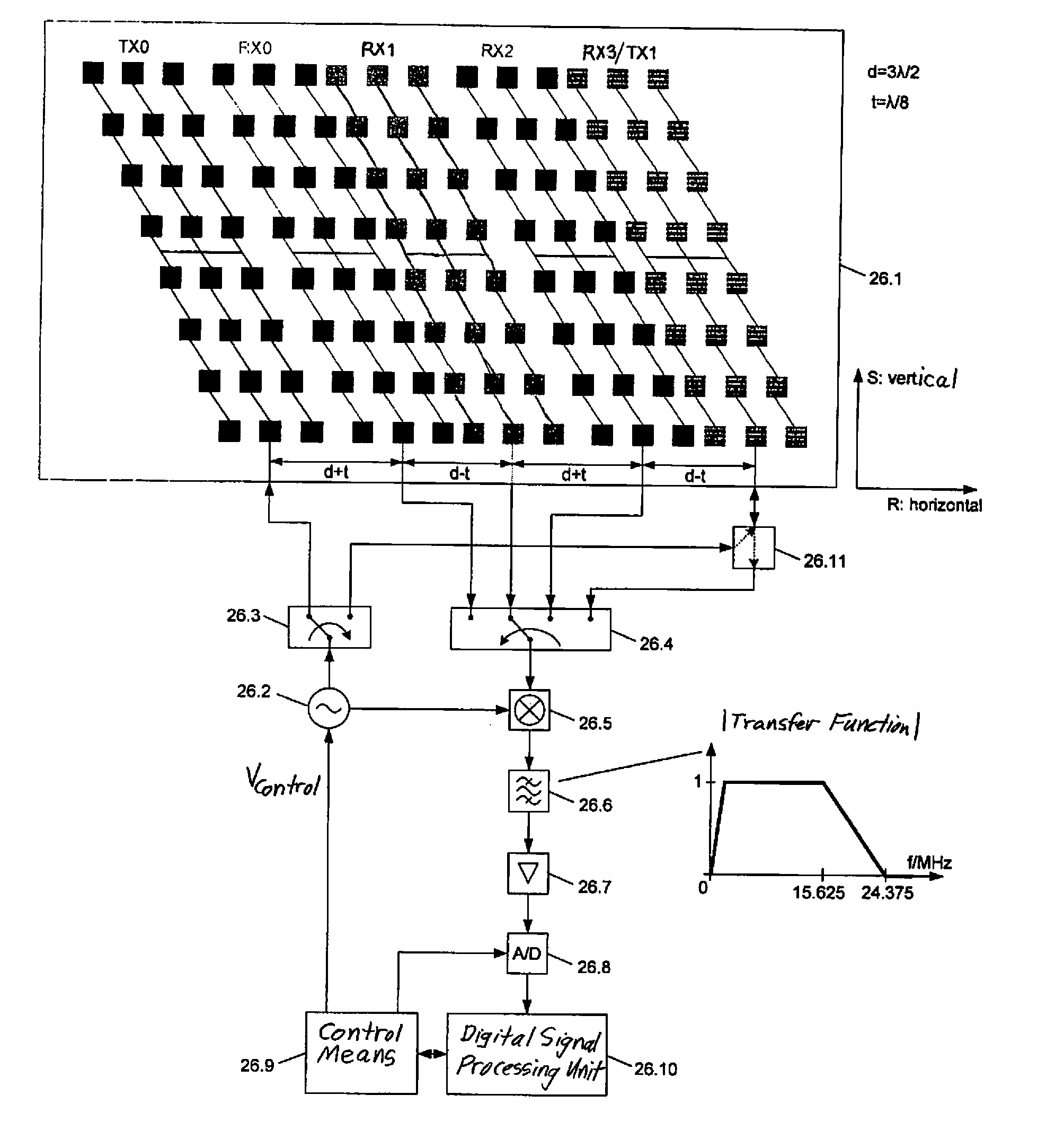
[0085]With the arrangements according to FIG. 1 and FIG. 10 considered so far, the transmitter antennas were arranged above the receiver antennas, since with an arrangement in one level (i.e. if the transmitter antennas would have been moved downward) the patches would have contacted each other, which cannot be realized. By the arrangement of the transmitter and receiver antennas one above the other, the latter can be only approx. half as high with a predetermined sensor height as with an arrangement in a plane, which in elevation direction leads to a smaller beam focusing and thus to a smaller antenna gain. By means of this on the one hand the vertical detection range increases, which can be disadvantageous for certain functions (e.g. because bridges can be hardly distinguished from stationary vehicles), and to the other hand the system sensitivity is reduced.
[0086]This limitation in the arrangement of the antennas can be avoided by the fact that at least one an...
PUM
 Abstract
Description
Claims
Application Information