Cannula with integrated camera and illumination

a technology of applied in the field of cannulas with integrated imaging and illumination devices, can solve the problems of lack of ability to obtain a viewing angle, prior art surgical instruments lack the ability to protect the optics of both imagers and illumination, etc., and achieves the effect of easy control of access, imaging and instrument use, and easy access control

Active Publication Date: 2013-05-14
ENDOSPHERE SURGICAL
View PDF79 Cites 317 Cited by
  • Summary
  • Abstract
  • Description
  • Claims
  • Application Information

AI Technical Summary

Benefits of technology

[0009]Prior art surgical instruments lack the ability to protect the optics of both imagers and illumination during insertion and lack the ability to obtain a viewing angle that is offset from the cannula axis. One purpose of the present invention is to make it easier to control the access, imaging, and instrument use during minimally invasive surgery, when using fewer incisions than typically necessary. By combining the cannula, imaging, and illumination, a single device can take the place of several, thereby allowing more efficient and more easily controlled access.
[0010]In one embodiment of the invention, a surgical apparatus includes combinations of trocar, cannula, and imaging and illumination components. In this embodiment, such combinations provide the surgeon with improved viewing of the surgical cavity. Alternative embodiments allow for reduced number of incisions on a patient.
[0011]The apparatus also allows for the development of improved surgical methods including reduced number of incisions, improved imaging of the surgical cavity, and / or improved performance of surgical effectiveness.
[0017]In another aspect, the invention relates to a method of using a cannula assembly including inserting a tubular element with a lumen into a body cavity, such that the tubular element has a proximal end and a distal end, and actuating a deployable portion of the tubular element about the distal end from a closed position to an open position, such that an electronic component mounted to the deployable portion is at least partially disposed in the lumen when the deployable portion is in the closed portion and the lumen is substantially free from obstruction when the deployable portion is in the open position.

Problems solved by technology

Prior art surgical instruments lack the ability to protect the optics of both imagers and illumination during insertion and lack the ability to obtain a viewing angle that is offset from the cannula axis.

Method used


Image

  • Cannula with integrated camera and illumination
  • Cannula with integrated camera and illumination
  • Cannula with integrated camera and illumination

Examples


Embodiment Construction

[0029]To provide an overall understanding of the invention, certain illustrative embodiments will now be described, including apparatus and methods for displaying images. However, it will be understood by one of ordinary skill in the art that the systems and methods described herein may be adapted and modified as is appropriate for the application being addressed and that the systems and methods described herein may be employed in other suitable applications. All such adaptations and modifications are to be considered within the scope of the invention.

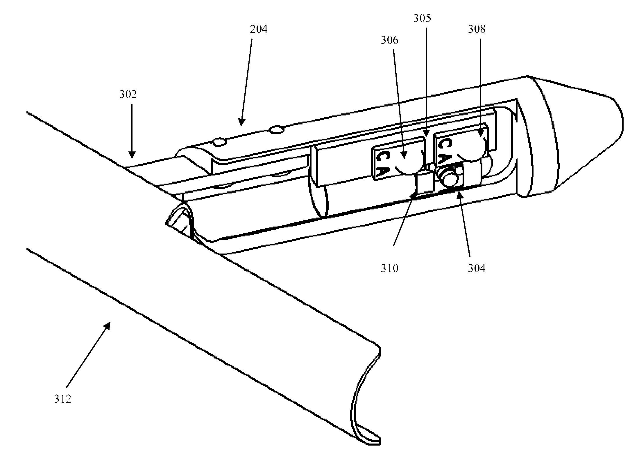
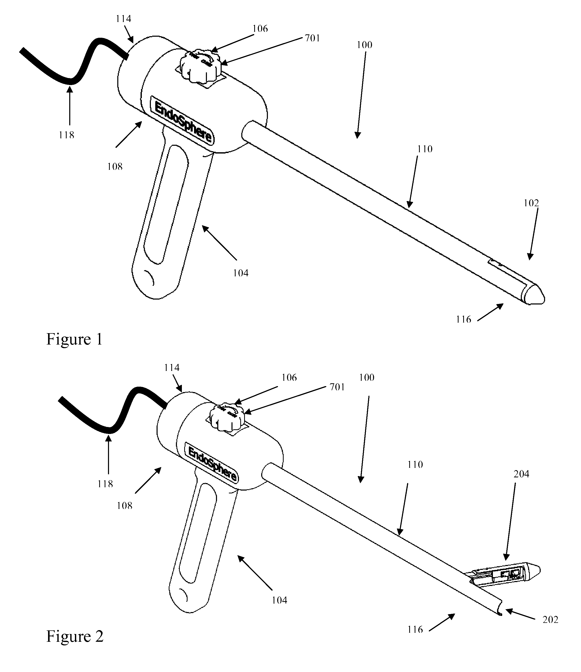
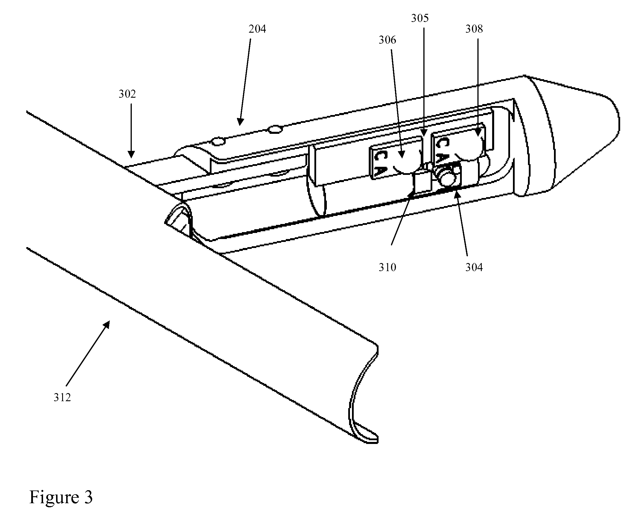
[0030]FIGS. 1 and 2 depict schematic perspective views of an embodiment of the cannula assembly 100 in closed and open positions, respectively. In one embodiment, the cannula assembly 100 includes a tubular element 110 forming a lumen 202. A proximal end 114 of the tubular element 110 can be adapted for manipulation by the surgeon or clinician, and a distal end 116 can be adapted for insertion into a body cavity. A housing 108 with a h...


PUM


Abstract

A cannula assembly includes a tubular element forming a lumen, a deployable portion of the tubular element, and an electronic component mounted to the deployable portion of the tubular element. The tubular element has a proximal end and a distal end adapted to be inserted into a body cavity. The deployable portion of the tubular element is engaged near the distal end of the tubular element so as to transition between a closed position and an open position. The electronic component is at least partially disposed in the lumen when the deployable portion is in the closed position.

Description

CROSS-REFERENCE TO RELATED APPLICATIONS[0001]This application claims priority to co-pending U.S. provisional patent application Ser. No. 61 / 164,215, titled “Cannula with embedded camera and illumination,” filed on Mar. 27, 2009, and U.S. provisional patent application Ser. No. 61 / 261,910, titled “Shape Memory Alloy Group, applications including SMA Clips, closures and Endoscope steering,” filed on Nov. 17, 2009, the disclosures of both of which are herein incorporated by reference in their entireties.TECHNICAL FIELD[0002]The present invention relates generally to cannulas with integrated imaging and illumination devices, more particularly to those configured with a deployable portion.BACKGROUND[0003]In minimally invasive surgery, there are often several small incisions made into the body to insert surgical tools, insufflation devices, endoscopes, or other viewing devices. Surgeons are now doing procedures in a manner that minimizes the number of incisions, possibly to only one, refe...

Claims


Application Information

Patent Timeline
Patent Type & Authority Patents(United States)
IPC IPC(8): A61B1/05
CPCA61B17/3421A61B17/3496A61B19/5202A61B2017/346A61B2017/3454A61B2017/3445A61B19/5212A61B90/30A61B90/361A61B1/00087A61B1/05A61B1/07
Inventor MCKINLEY, ARTHUR C.PRENOVITZ, MELVIN B.MCKINLEY, PHILIP E.PLOUFFE, JESSE R.
Owner ENDOSPHERE SURGICAL
Why Eureka
Try Eureka