
Amplifier optical fiber comprising nanoparticles and production method

a nanoparticle and optical fiber technology, applied in the field of optical fibers, can solve the problems of complex and expensive stabilized laser sources that must be used, require the use of very powerful lasers which are expensive, and achieve the effect of improving signal amplification

Inactive Publication Date: 2013-05-14
DRAKA COMTEQ BV
View PDF16 Cites 1 Cited by
  • Summary
  • Abstract
  • Description
  • Claims
  • Application Information

AI Technical Summary

Benefits of technology

[0025]According to the embodiments, the doping element of the core is a rare earth or a combination of rare earths; for example erbium. The dielectric matrix of the central core can be silica. The central core can also comprise a doping element for improving the signal amplification.

Problems solved by technology

The 980 nm wavelength is usually used for low-noise equipment but the corresponding absorption window is relatively narrow, thus stabilized laser sources which are complex and expensive must therefore be used.
The absorption window of the 1480 nm wavelength is wider but requires the use of very powerful lasers which are expensive.
This solution is however limited to relatively high pumping wavelengths.
This solution is however limited by the problem of maintaining the semi-conductor element in the reduced state.
For the two solutions of the prior art described above, the effectiveness of the energy transfer to the erbium atoms is limited to the closest neighbours, i.e. a distance of a few nanometers between the active species.
Moreover, the energy transfer between the power of the pump signal and the emission by the Er3+ ions is limited to approximately 40%.
However, this solution is not directly transposable to an application with optical fibers due to the incompatibility between the melting point of silver and the production temperature of the optical fibers.
The production constraints of the optical fibers impose choices on the nature, size and shape of the incorporated nanostructures.

Method used


Image

  • Amplifier optical fiber comprising nanoparticles and production method
  • Amplifier optical fiber comprising nanoparticles and production method
  • Amplifier optical fiber comprising nanoparticles and production method

Examples


first embodiment

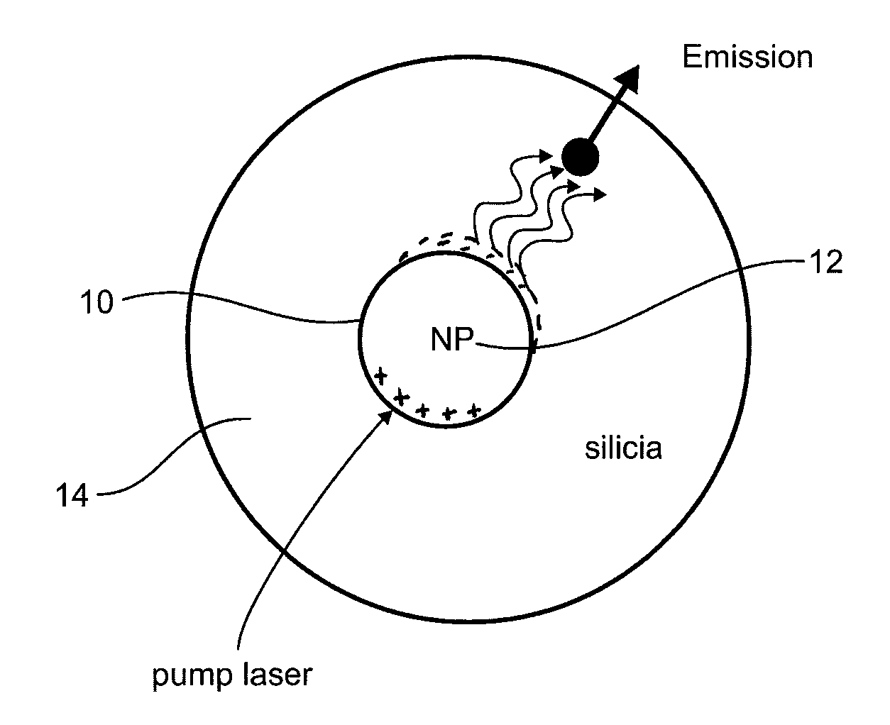
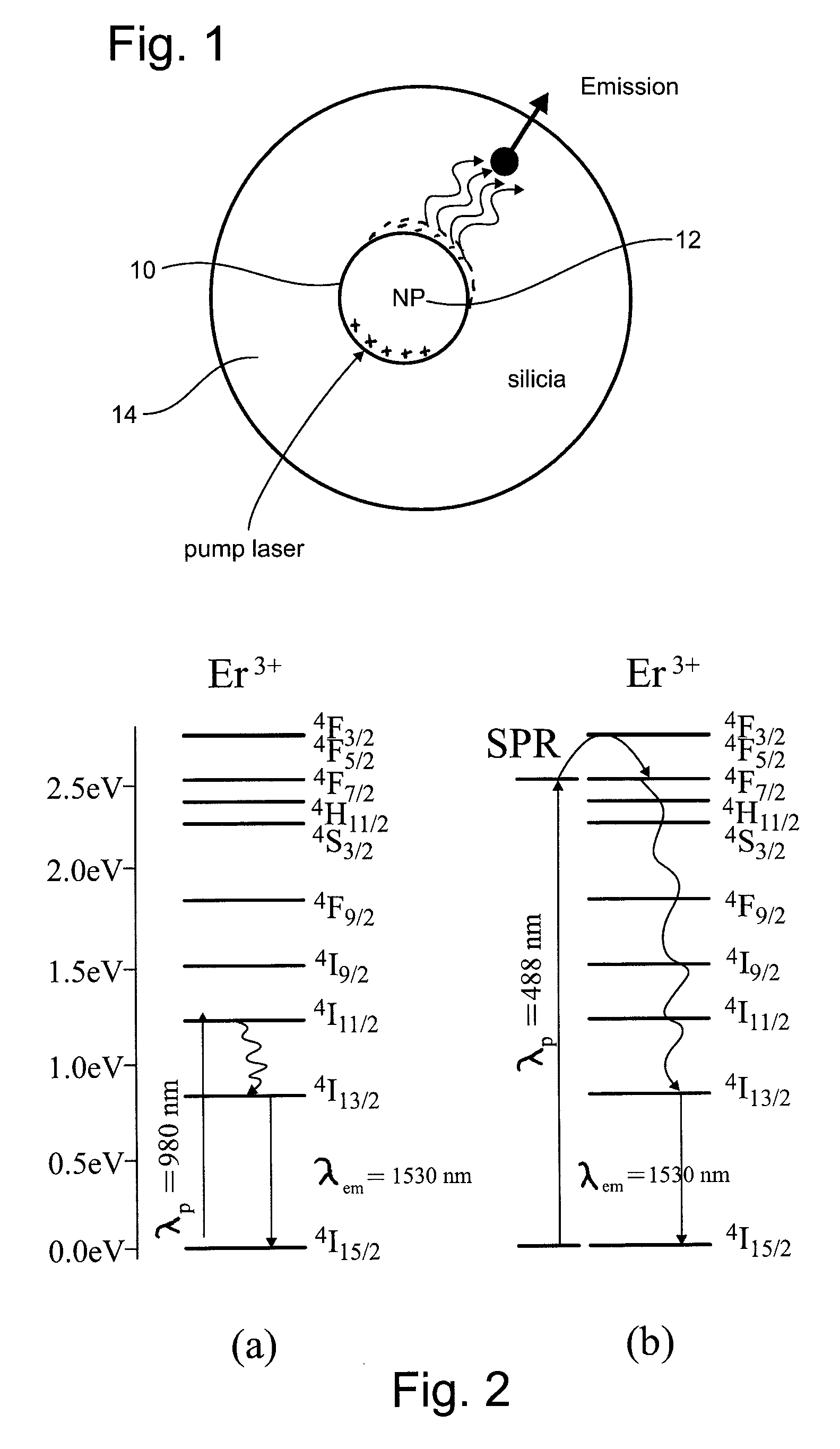
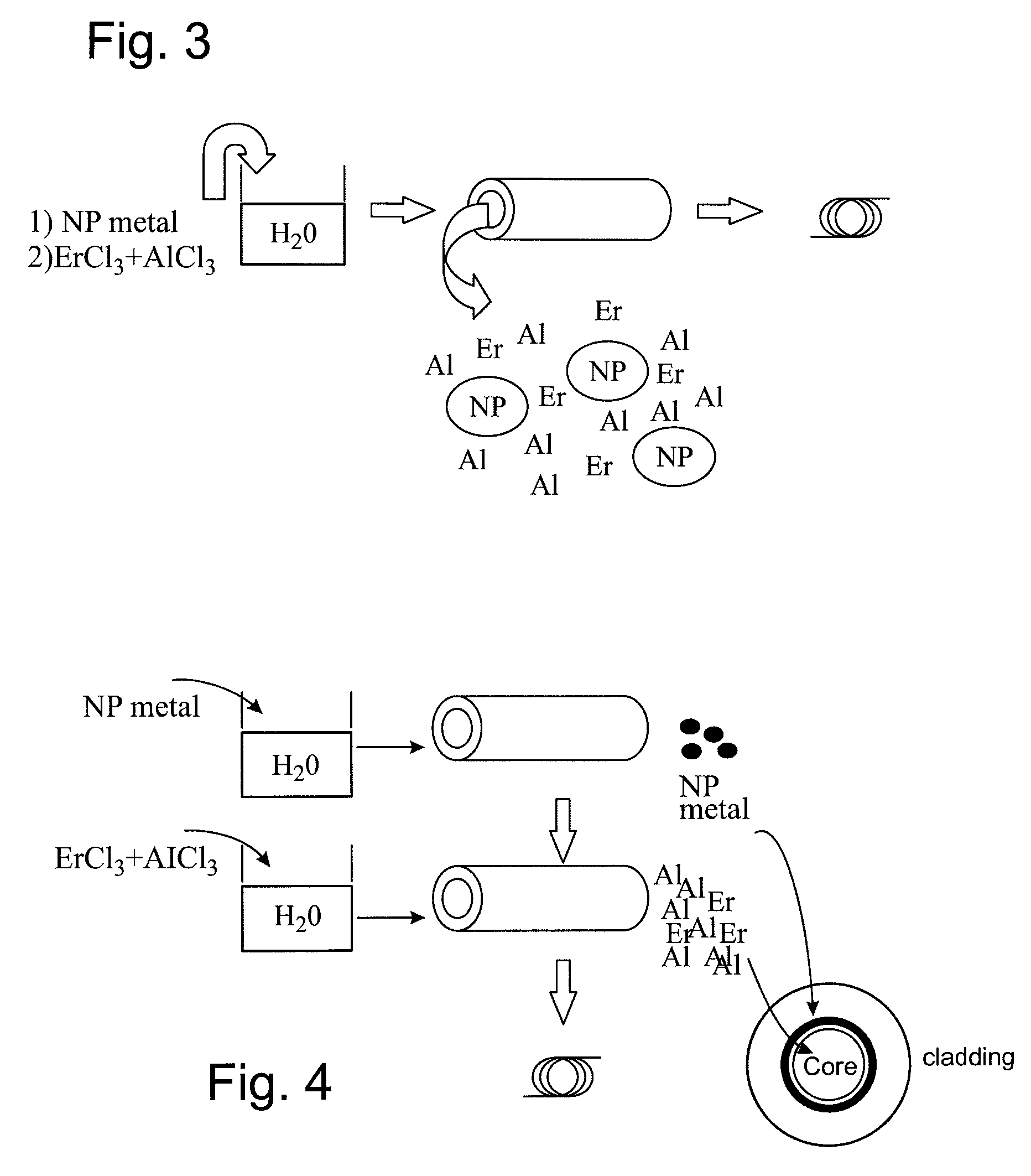
[0075]FIG. 3 illustrates an optical fiber according to the invention in which metallic nanostructures are incorporated into the Aluminium / Erbium co-doped core of a fiber. An erbium-doped aluminosilicate fiber comprising metallic nanostructures is then obtained. In this embodiment, the electron resonance wavelength will depend on the electron charge density, i.e. on the metal used, and on the diameter of the metallic nanostructures.

[0076]The metallic nanostructures nanoparticles can be produced by chemical or physical synthesis and dispersed in an aqueous solution. The erbium and aluminium dopants are then mixed with this solution by dissolution of their chlorinated precursors. The chlorinated precursors and the nanoparticles are then incorporated by the impregnation of a porous silica rod during an MCVD operation in order to obtain a preform from which an optical fiber can be formed.

second embodiment

[0077]In a second embodiment, illustrated in FIG. 4, the metallic nanostructures nanoparticles can be introduced into the vicinity of the erbium-doped core, at the core-cladding interface, in the form of a ring doped with metallic nanostructures. This embodiment makes it possible to further limit the losses by absorption while ensuring a sufficient proximity between the erbium atoms and the metallic nanostructures in order to guarantee the energy transfer by SPR effect. The metallic nanostructures nanoparticles produced by chemical or physical synthesis are dispersed in an aqueous solution; and the erbium and aluminium dopants are dissolved in a separate solution. The doping elements (Al, Er) then the metallic nanostructures (NP) are then incorporated by impregnation of a porous silica rod during an MCVD operation in order to obtain a preform from which an optical fiber can be formed.

third embodiment

[0078]FIG. 5 illustrates an optical fiber according to the invention in which nanostructures formed from an assembly of aluminium and erbium atoms are coated with a metallic layer. A fiber comprising Al / Er nanoparticles surrounded by a metallic coating is then obtained. In this embodiment, the electron resonance wavelength will depend on the electron charge density, i.e. on the metal used, the thickness of the metallic layer and the external diameter of the nanostructures. For example, in the publication of J. Aizpurua et al., Phys Rev Lett. vol 90 No. 5, 2003, cited above, it has been demonstrated for rings of gold with an external diameter of 60 nm that the resonance wavelength shifts from 700 nm towards 1400 nm when the thickness of the ring passes from 14 nm to 9 nm. Al / Er nanoparticles can be produced by chemical or physical synthesis leading to a powder of nanoscopic grains. The powder is then coated with a metallic layer by chemical or physical synthesis. The metal coating ca...


PUM

PropertyMeasurementUnit
diameteraaaaaaaaaa
melting pointaaaaaaaaaa
evaporating temperatureaaaaaaaaaa

Abstract

An amplifier optical fiber comprising a central core of a dielectric matrix doped with at least one element ensuring the amplification of an optical signal transmitted in the fiber and a cladding surrounding the central core and suitable for confining the optical signal transmitted in the core. The fiber also comprises metallic nanostructures suitable for generating an electronic surface resonance in the dielectric matrix of central core, the wavelength of said electronic surface resonance corresponding to an excitation level of the element ensuring the amplification.

Description

FIELD OF THE INVENTION[0001]The present invention relates to the field of optical fibers, and more specifically, an amplifier optical fiber suitable for amplifying the optical signals transmitted. The amplifier fibers can be used in particular as high bandwidth transmission line amplifiers or as lasers. The invention also relates to a method for producing such a fiber.BACKGROUND OF THE INVENTION[0002]Amplifier fibers, and in particular fibers doped with rare earth elements such as erbium, are commonly used in long haul optical telecommunication systems in order to amplify transmitted optical signals. Such fibers are used in EDFAs (Erbium Doped Fiber Amplifiers) and have a central core composed of a silica matrix comprising Erbium doping elements optionally combined with complementary doping elements making it possible to improve the amplification.[0003]In a manner known per se, optical amplification in an EDFA-type fiber operates by injecting into the fiber a pump signal which excit...

Claims


Application Information

Patent Timeline
Patent Type & Authority Patents(United States)
IPC IPC(8): G02B6/02
CPCC03C3/06H01S3/06754C03C4/10C03C4/12C03C13/045C03C14/004C03C14/006C03C4/0071C03C2201/30C03C2201/32C03C2201/3476C03C2201/36C03C2203/40H01S3/06708H01S3/06716C03B37/01838C03B2201/34C03B2201/58Y02P40/57
Inventor BUROV, EKATERINAPASTOURET, ALAINGASCA, LAURENTCOLLET, CHRISTINE
Owner DRAKA COMTEQ BV
Learn More