Optical information reproducing apparatus
A regeneration device and optical information technology, applied in information storage, recording information storage, optical recording head, etc., can solve the problems of the detection signal S/N ratio reduction, the inability to fully ensure the reproduction signal S/N ratio, etc., and achieve the effect of signal amplification high effect
- Summary
- Abstract
- Description
- Claims
- Application Information
AI Technical Summary
Problems solved by technology
Method used
Image
Examples
Embodiment 1
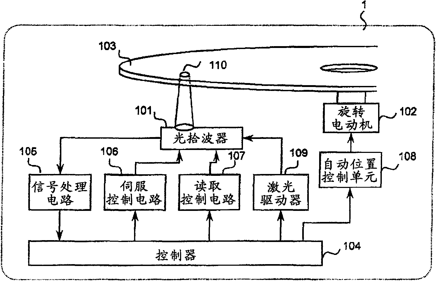
[0045] figure 1 It is a diagram showing an example of the overall configuration of an optical information recording and reproducing apparatus for realizing the optical signal detection method of the present invention.
[0046] [Overall structure of optical information recording and reproducing device]
[0047] The optical information recording and reproducing apparatus 1 includes an optical pickup 101 and a rotary motor 102 , and the optical information recording medium 103 can be rotated by the rotary motor 102 .
[0048] The optical pickup 101 plays a role of irradiating light onto the optical information recording medium 103 to record and / or reproduce digital information. The reproduced light detected by the optical pickup 101 is input to the signal processing circuit 105 after current-voltage (IV) conversion. A reproduction signal or a servo signal is generated by the signal processing circuit 105 and sent to the controller 104 .
[0049] The controller 104 controls the...
Embodiment 2
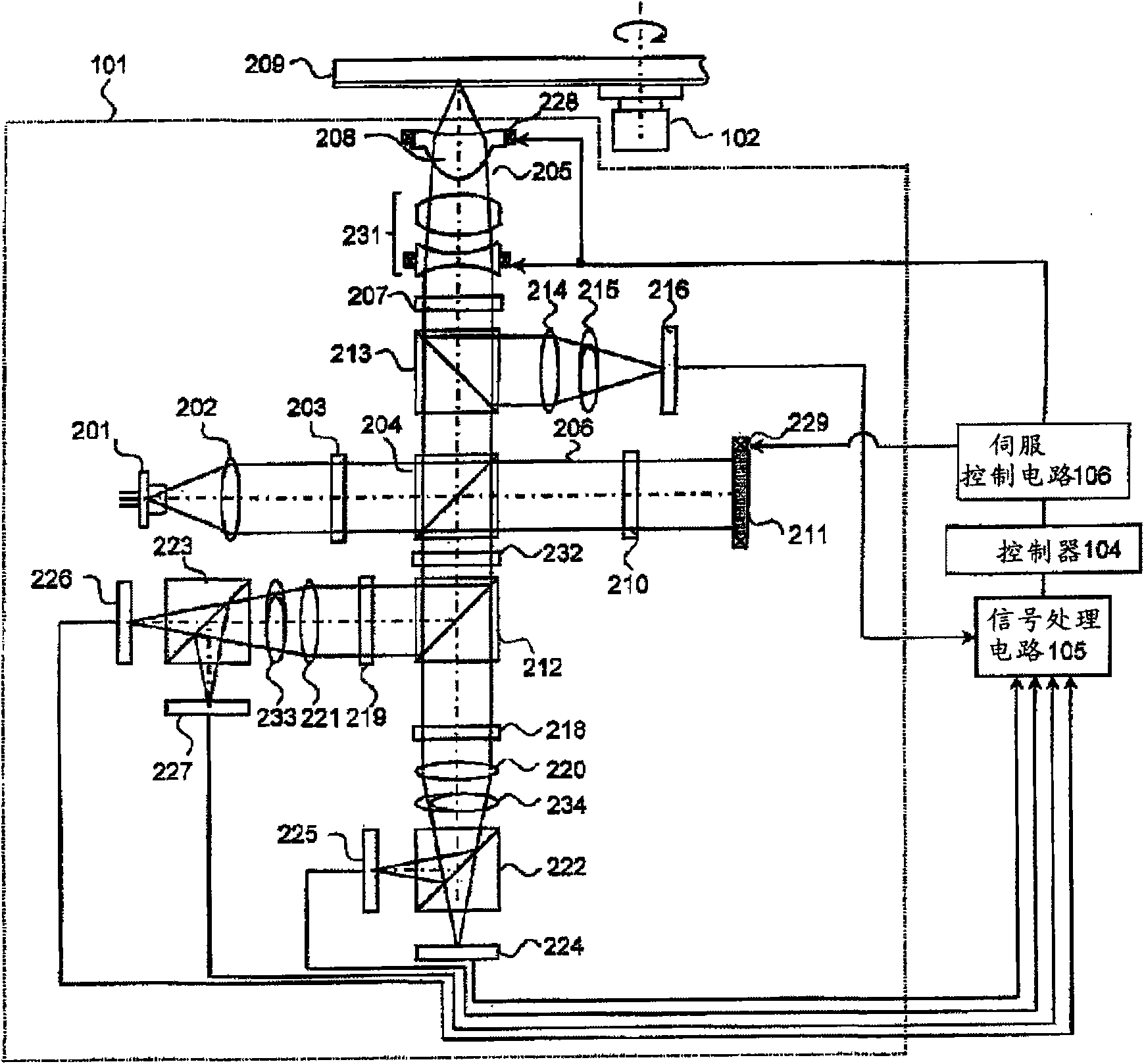
[0103] In this embodiment, an example of an optical information recording and reproducing apparatus that implements an optical signal detection method that detects not only focus error signals but also tracking error signals from the photodetectors 224, 225, 226, and 227 will be described. In addition, regarding the optical information recording and reproducing apparatus 1 and the optical pickup 101 in this embodiment, descriptions are given and given. figure 1 , figure 2 The description of the parts with the same symbols and the same functions will be omitted.
[0104] Figure 9 It is a diagram showing another example of the structure of the light splitting element 232 of the optical pickup 101 in the optical information recording and reproducing apparatus 1 . The light splitting element 232 is bounded by a relatively small diameter 502 relative to the diameter of the incident light beam 501 , so that the directions of the diffraction gratings are different in the inner re...
Embodiment 3
[0111] In Embodiments 1 and 2, the case where the astigmatism method is used as the focus error signal detection method is shown, but in this embodiment, an example of an optical information recording and reproducing apparatus using the branch-and-edge method will be described. When using the astigmatism method in the optical pickup 101, as figure 2 Cylindrical lenses 233, 234 are configured as shown, but are not required when using the prism method. In addition, at this time, the photodetectors 224 , 225 , 226 , and 227 are arranged at the focal positions of the condensing lenses 220 , 221 .
[0112] Figure 12 It is a diagram showing another example of the structure of the light splitting element 232 of the optical pickup 101 in the optical information recording and reproducing apparatus 1 . The spectroscopic element 232 sets a boundary with a relatively small diameter 502 relative to the diameter of the incident light beam 501, and divides its inner region into upper and...
PUM
 Abstract
Description
Claims
Application Information
 - R&D
- Intellectual Property
- Life Sciences
- Materials
- Tech Scout
- Unparalleled Data Quality
- Higher Quality Content
- 60% Fewer Hallucinations
Browse by: Latest US Patents, China's latest patents, Technical Efficacy Thesaurus, Application Domain, Technology Topic, Popular Technical Reports.
© 2025 PatSnap. All rights reserved.Legal|Privacy policy|Modern Slavery Act Transparency Statement|Sitemap|About US| Contact US: help@patsnap.com


