Articulated arm robot, control method and control program

a robot and arm technology, applied in the field of articulated arm robots, can solve the problems of power consumption and unsafe arm structure, and achieve the effect of small driving force and simple structur

Active Publication Date: 2013-05-14
TOYOTA JIDOSHA KK
View PDF26 Cites 26 Cited by
  • Summary
  • Abstract
  • Description
  • Claims
  • Application Information

AI Technical Summary

Benefits of technology

[0025]According to the present invention, it is possible to provide an articulated arm robot capable of driving an arm with a small driving force and movable over a wide range in a simple structure, a control method, and a control program.

Problems solved by technology

This results in the arm structure which is not very safe and not low power consumption.

Method used


Image

  • Articulated arm robot, control method and control program
  • Articulated arm robot, control method and control program
  • Articulated arm robot, control method and control program

Examples


first embodiment

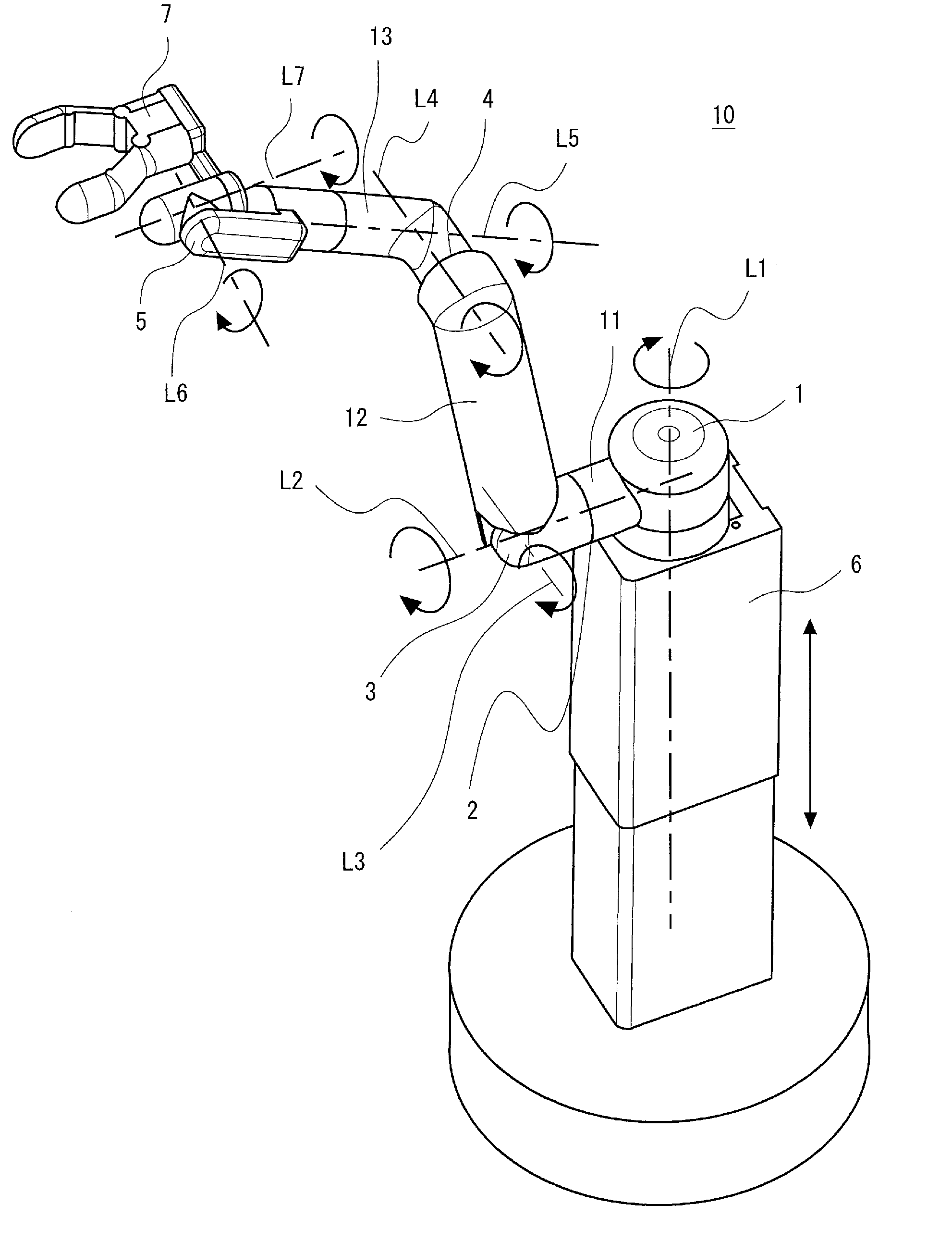
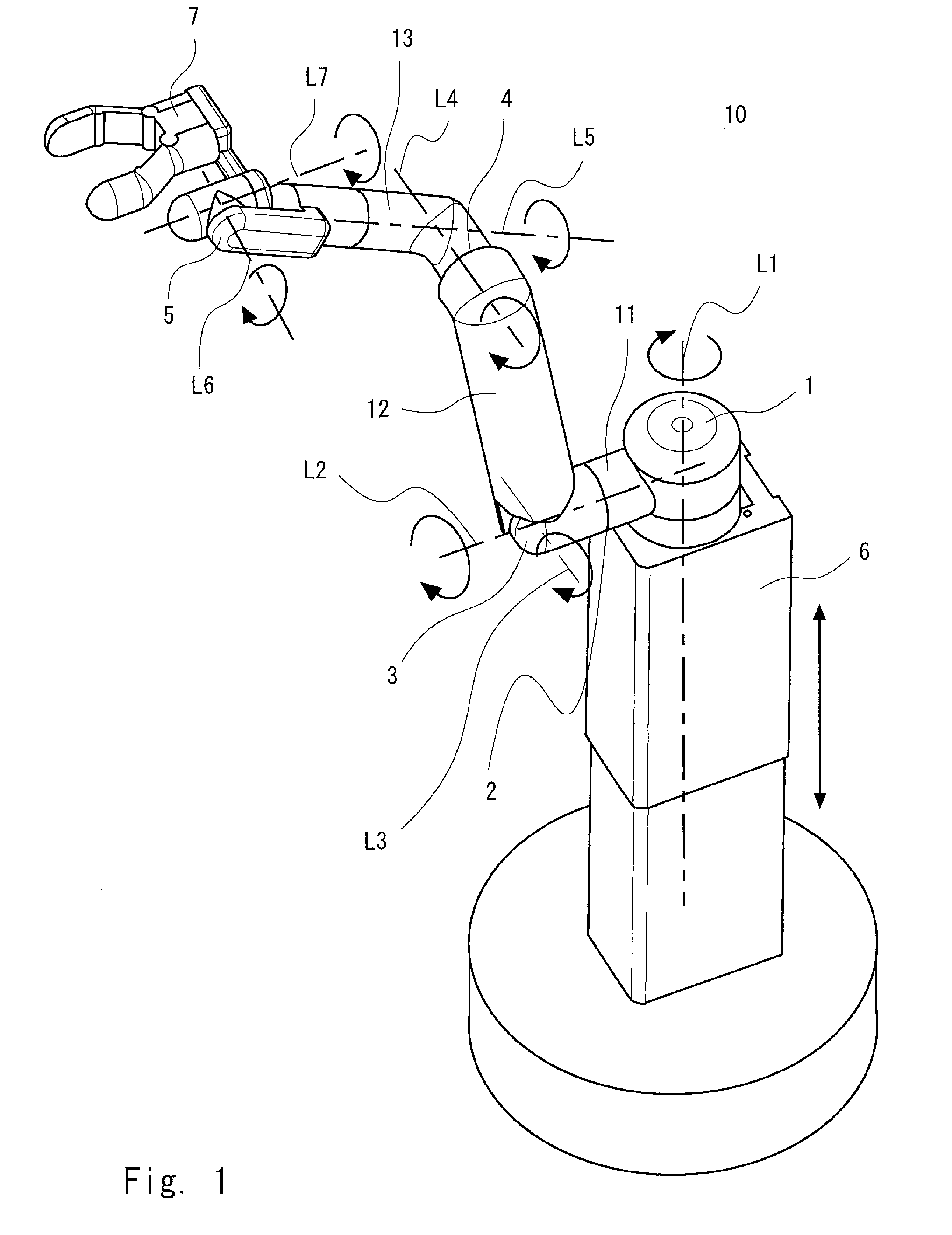
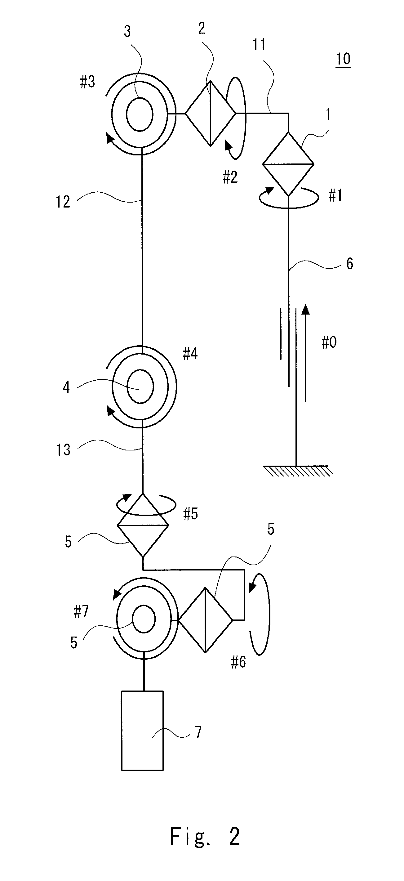
[0048]Embodiments of the present invention are described hereinafter with reference to the drawings. FIG. 1 is a perspective view showing a schematic structure of an articulated arm robot according to a first embodiment of the present invention. FIG. 2 is a block diagram showing a schematic arm structure of the articulated arm robot according to the first embodiment. FIG. 3 is a block diagram showing a schematic system configuration of the articulated arm robot according to the first embodiment.

[0049]An articulated arm robot 10 according to the first embodiment includes a support part 6 fixed to a given position, a first arm part 11 with one end joined to the top end of the support part 6 through a first joint 1, a second arm part 12 with one end joined to the other end of the first arm part 11 through a third joint 3, a third arm part 13 with one end joined to the other end of the second arm part 12 through a fourth joint 4, an end effector part 7 joined to the other end of the thi...

second embodiment

[0073]In the articulated arm robot 10 according to a second embodiment of the present invention, the controller 8 controls the rotation of the first, third and fourth joints 1, 3 and 4 by controlling the first, third and fourth drivers 21, 23 and 24 to minimize the torque imposed on the roll axis L2 of the second joint 2 in the SCARA mode. In the SCARA mode, a large torque is likely to act on the roll axis L2 of the second joint 2; however, by minimizing the torque of the second joint 2, the second driver 22 with a small driving force can be employed, which allows the improved safety and lower power consumption of the arm.

[0074]For example, the controller 8 controls the rotation of the first, third and fourth joints 1, 3 and 4 by controlling the first, third and fourth drivers 21, 23 and 24 so as to minimize a moment force (moment length X1) by the center of gravity position G of the second joint 2 to the end effector part 7 (FIG. 13).

[0075]Next, an example of a method of minimizing...

third embodiment

[0089]In the articulated arm robot 10 according to a third embodiment of the present invention, the controller 8 controls the rotation of the third and fourth joints 3 and 4 by controlling the third and fourth drivers 23 and 24 to minimize the torque imposed on the pitch axis L3 of the third joint 3 in the perpendicular mode. In the perpendicular mode, a large torque is likely to act on the third joint 3; however, by minimizing the torque of the third joint 3, the third driver 23 with a small driving force can be employed, which achieves the improved safety and lower power consumption of the arm.

[0090]For example, the controller 8 controls the rotation of the third and fourth joints 3 and 4 by controlling the third and fourth drivers 23 and 24 by selecting a solution of the inverse kinematics with a smaller moment force (moment length X2) around the pitch axis L3 of the third joint 3 by the center of gravity position G from the third joint 3 to the end effector part 7.

[0091]To be mo...


PUM


Abstract

An articulated arm robot includes a support part capable of extending and contracting upward and downward, a first arm part with one end joined to the support part through a first joint to be rotatable about a yaw axis and having a second joint rotatable about a roll axis between both ends, a second arm part with one end joined to the other end of the first arm part through a third joint to be rotatable about the yaw axis or a pitch axis, an end effector part joined to the other end of the second arm part through a fourth joint to be rotatable about the yaw axis or the pitch axis, and drivers that respectively cause the first to fourth joints to rotate and the support part to extend and contract, and a controller that performs drive control of the drivers of the first to fourth joints by switching the arm between a SCARA mode where the first, second and third arm parts rotate only in a horizontal plane and a perpendicular mode where the second and third arm parts rotate only in a vertical plane.

Description

[0001]This is a 371 national phase application of PCT / JP2011 / 000523 filed 31 Jan. 2011, the contents of which are incorporated herein by reference.TECHNICAL FIELD[0002]The present invention relates to an articulated arm robot having a plurality of joints, a control method, and a control program.BACKGROUND ART[0003]In general, an arm robot that works together with human is required to have high safety, and, in order to safely operate the arm robot, it is desirable to sufficiently reduce its driving force and assure the safety. However, to achieve both a wider range of motion and a heavier work weight capacity using a typical vertical articulated arm with an arm axis structure similar to a human arm, a large driving force is required especially at a joint of the arm base where a moment length is long. This results in the arm structure which is not very safe and not low power consumption.[0004]On the other hand, assembly work or the like is performed using an industrial robot such as a...

Claims


Application Information

Patent Timeline
Patent Type & Authority Patents(United States)
IPC IPC(8): G05B15/00G05B19/00G05B19/18
CPCB25J9/06B25J3/00B25J9/047B25J9/042
Inventor SAITO, FUMINORIISOBE, TORU
Owner TOYOTA JIDOSHA KK
Why Eureka
Try Eureka