Traction control system and method

a technology of traction control system and traction control method, applied in the direction of process and machine control, external condition input parameters, navigation instruments, etc., can solve the problems of low implementation rate and recognized disadvantages of such an approach, and achieve the effect of improving vehicle performan

Active Publication Date: 2013-05-14
FORD GLOBAL TECH LLC
View PDF11 Cites 39 Cited by
  • Summary
  • Abstract
  • Description
  • Claims
  • Application Information

AI Technical Summary

Benefits of technology

[0004]In this way, for example, it is possible to utilize the information to improve vehicle performance on variable friction surfaces, without having to first identify the variation in friction.

Problems solved by technology

However, the inventors herein have recognized a disadvantage with such an approach.
For example, platooned vehicles may require significant regulation, and thus, the rate of implementation may be rather low.

Method used


Image

  • Traction control system and method
  • Traction control system and method
  • Traction control system and method

Examples


Embodiment Construction

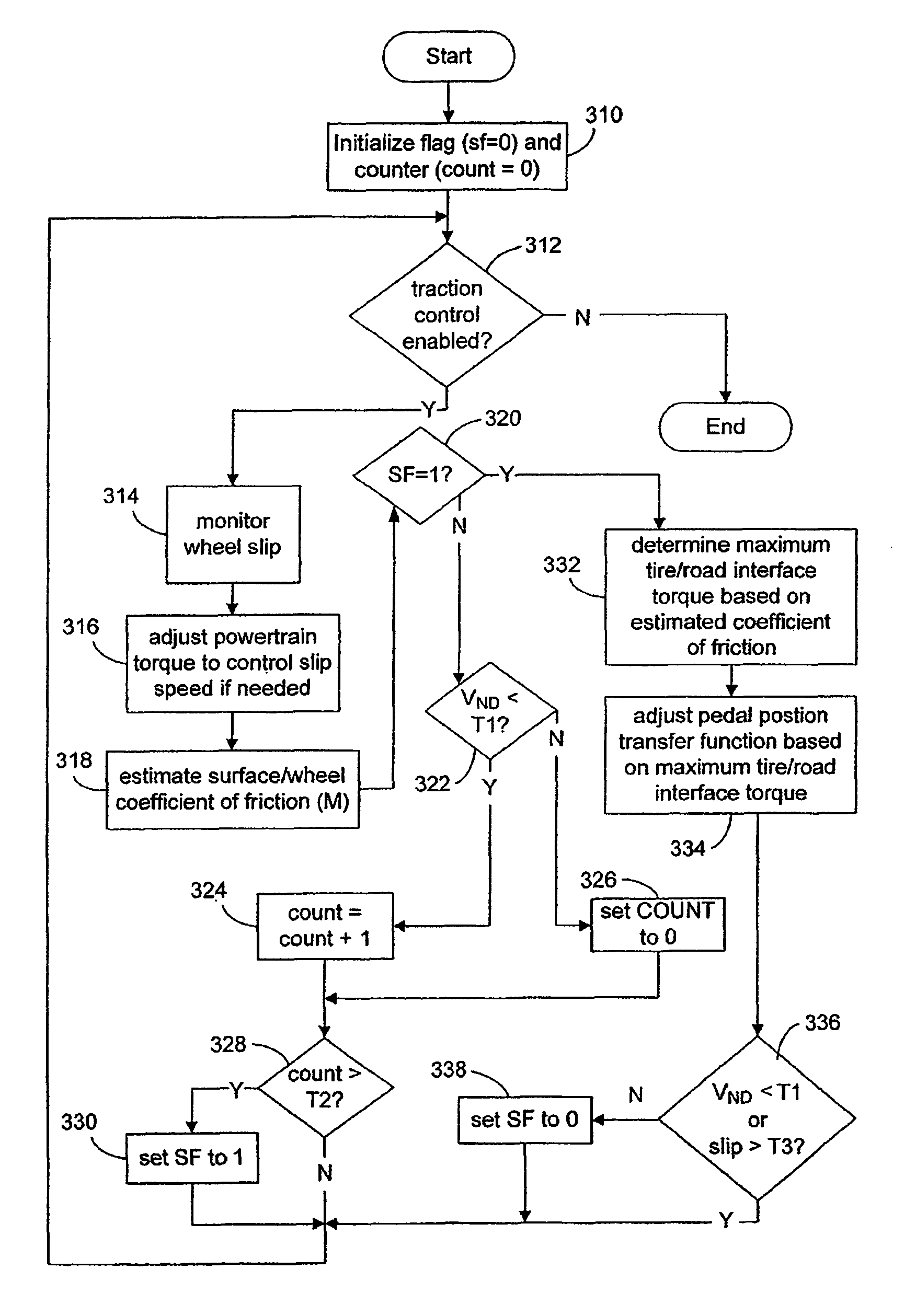
[0011]Traction control systems may be used to adjust powertrain output to improve vehicle operation in situations that may result in reduced traction between a vehicle's wheel and the road. As noted above, a non-moving vehicle situation can be especially challenging where even limiting powertrain output and controlling wheel slip may not result in any significant movement of the vehicle. The following disclosure addresses such a situation, as well as others.

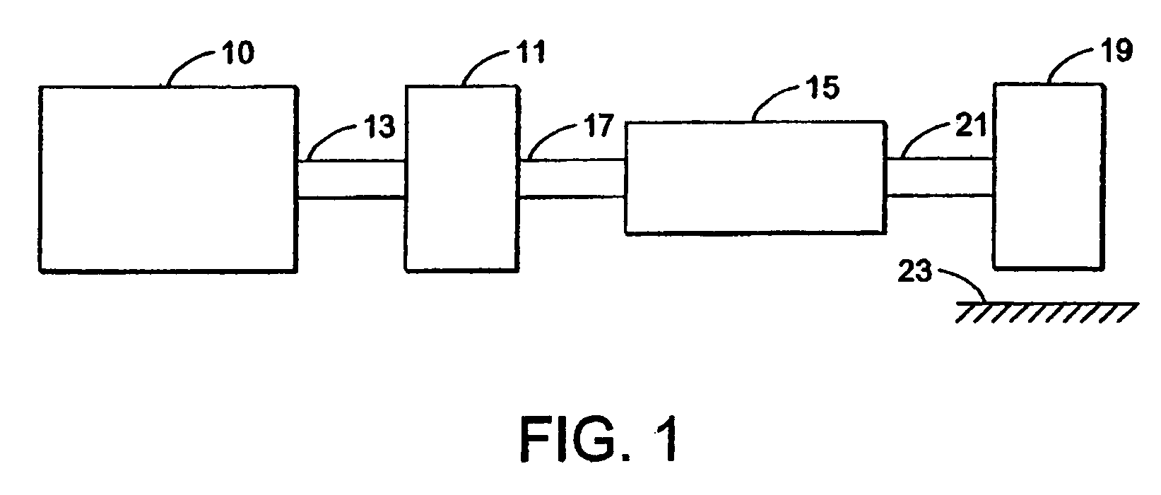
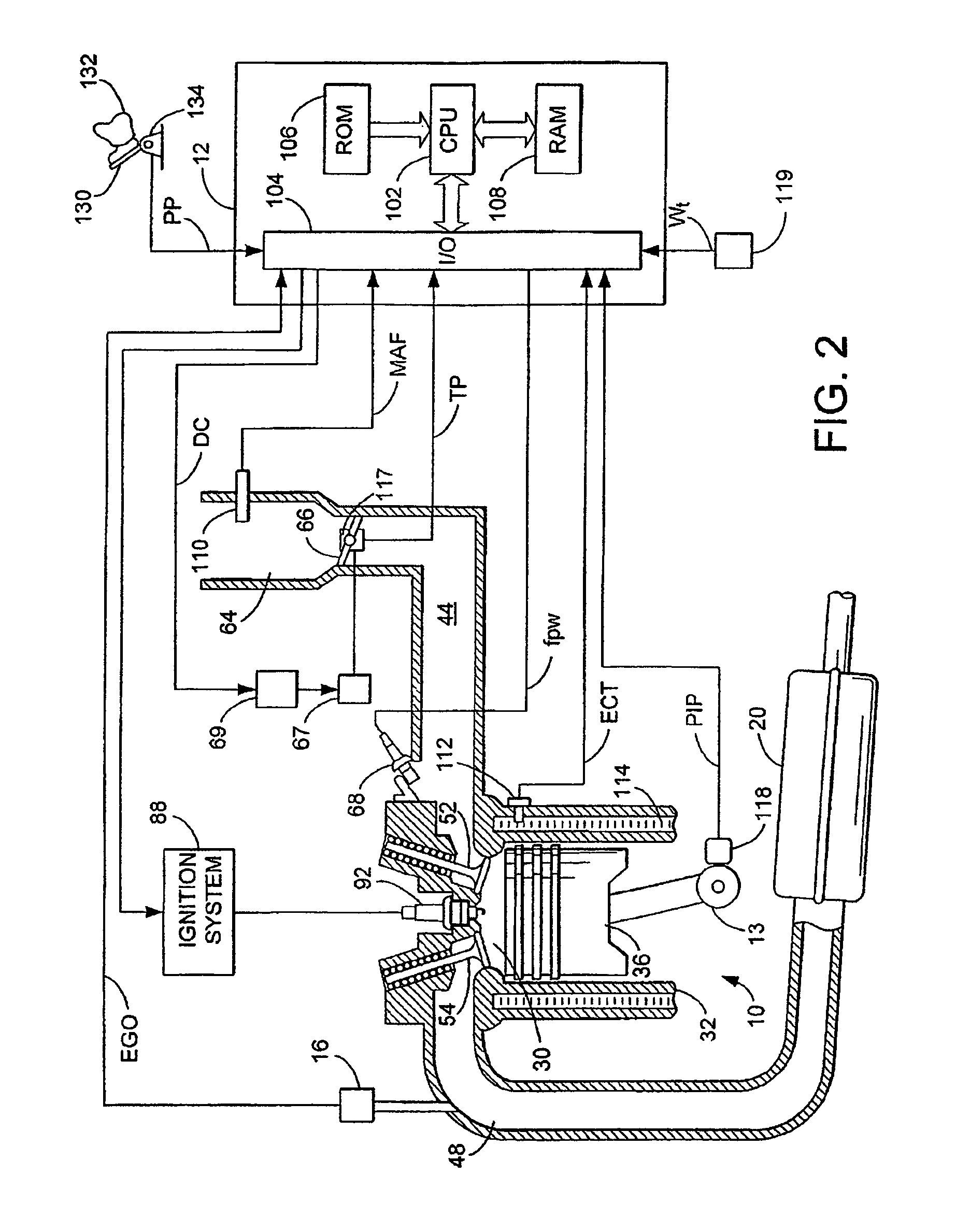
[0012]Referring to FIG. 1 an example powertrain of a vehicle is shown. Specifically, internal combustion engine 10, further described herein with particular reference to FIG. 2, is shown coupled to torque converter 11 via crankshaft 13. Torque converter 11 may also coupled to transmission 15 via transmission input shaft 17. Torque converter 11 may have a bypass clutch, which can be engaged, disengaged, or partially engaged. When the clutch is either disengaged or partially engaged, the torque converter is said to be in an unlocke...


PUM


Abstract

In one example, a first vehicle traveling on a road is provided. The vehicle comprises a communication device coupled in the first vehicle configured to receive information transmitted by a second vehicle traveling on the road, the information identifying road surface conditions experience by the second vehicle; and a controller configured to adjust a vehicle operating parameter of the first vehicle in response to receiving the transmitted information from the second vehicle.

Description

BACKGROUND AND SUMMARY[0001]Advanced vehicle communication approaches have been used to develop “platooned” vehicle groups, where a group of vehicles travels in a platoon on the highway under automatic control. Such vehicles utilize communication between the vehicles, where there is typically a lead vehicle that transmits its speed, acceleration, desired traveling distance between vehicles, and other data to the other vehicles in the platoon. The trailing vehicles use this information, along with other measured data, to maintain the platoon under desired conditions. Such platoons attempt to increase highway throughput by utilizing automatic control.[0002]However, the inventors herein have recognized a disadvantage with such an approach. For example, platooned vehicles may require significant regulation, and thus, the rate of implementation may be rather low. However, the inventors herein have also recognized that communication from one vehicle to another under less stringent require...

Claims


Application Information

Patent Timeline
Patent Type & Authority Patents(United States)
IPC IPC(8): G06F7/70
CPCB60T8/172B60W10/06B60W10/10B60W30/165B60T2210/12B60W2550/14B60W2550/142B60W2550/148B60W2550/408B60W2552/40B60W2556/65B60W2552/00B60W2552/15B60W2552/05
Inventor HROVAT, DAVORFODOR, MICHAELMCCONNELL, MITCH
Owner FORD GLOBAL TECH LLC
Why Eureka
Try Eureka