Explosion forming system

a technology of forming system and forming plate, which is applied in the direction of forging press, forging/pressing/hammering apparatus, manufacturing tools, etc., can solve the problems of reducing the production rate of parts, requiring significant amount of energy to operate, and the proposed system for this purpose suffers several problems, so as to reduce the power required for pressing the die, reduce the capital cost, and reduce the effect of tonnag

Active Publication Date: 2013-05-21
MAGNA INTERNATIONAL INC
View PDF37 Cites 2 Cited by
  • Summary
  • Abstract
  • Description
  • Claims
  • Application Information

AI Technical Summary

Benefits of technology

[0007]The nature of the explosion is an important factor in determining the overall cost of an explosion forming system. In one broad aspect of the invention, an explosion forming system is provided where the system generates a shock wave that is progressively applied to a work piece. This enables the tonnage required to press or seal a conforming die for the work piece to be reduced in comparison to other pressure forming systems such as hydro-forming systems or other explosion forming systems. This is primarily due to the fact that the force of the shock wave, although relatively high as discussed in detail herein, is applied over a relatively small area of the work piece and underlying die at any point in time, and thus the power required to press the die can be reduced in comparison to prior art pressure forming systems. Smaller tonnage means reduced capital costs. In addition, by progressively applying a shock wave, it is easier to punch relatively small holes in the work piece and / or trim sections of the work piece in comparison to the prior art.
[0014]As discussed in detail herein, another factor in reducing the tonnage required to press the die in an explosion forming system lies in the after pressure or back pressure resulting from the gaseous products of combustion. To minimize such after pressure, it is desirable to use a stoichiometric ratio of oxygen and hydrogen to produce water vapour, and to cool the ignition chamber in order to rapidly condense the water vapour and hence reduce the after pressure.
[0016]Sixth, an apparatus for modifying a tubular work piece defining a conduit length. The apparatus includes: an ignition chamber configured for generating a shock wave that has a shock wave length that is less than the conduit length of the work piece, wherein the ignition chamber utilizes oxygen and hydrogen as combustibles and includes at least one combustibles inlet; an igniter; a die, wherein the die includes a first die plate and a second die plate, wherein at least one of the first and second die plates is movable relative to the other between an open position and a closed position wherein the first and second die plates together define a die cavity in which the work piece can be positioned, wherein, in operation, the shock wave travels through the work piece and applies a localized pressure to the work piece in a direction that is transverse to the shock wave travel path, and wherein the die is holdable in the closed position by a selected die holding force against pressure in the work piece; a transfer structure configured to convey the shock wave from the ignition chamber into the work piece to modify the work piece; a controller for the transfer of a selected ratio and quantity of oxygen and hydrogen combustibles into the ignition chamber and for actuating the igniter to react the combustibles, wherein the controller serially executes explosions; and a cooling system for cooling the ignition chamber so as to reduce the pressure of water vapour created by reacting oxygen and hydrogen.
[0017]Seventh, an apparatus for modifying a work piece having a longitudinal length. The apparatus includes: an ignition chamber configured for generating a traveling shock wave that has a shock wave length that is less than the longitudinal length of the work piece, wherein the ignition chamber utilizes oxygen and hydrogen combustibles to generate the shock wave and includes at least one combustibles inlet; an igniter; a die, wherein the die includes a first die plate and a second die plate, wherein at least one of the first and second die plates is movable relative to the other between an open position and a closed position wherein the first and second die plates together define a die cavity in which the work piece can be positioned; a transfer structure configured to convey the shock wave from the ignition chamber into the die cavity; wherein, in operation, the shock wave applies a localized pressure to the work piece in a direction that is transverse to the direction of travel of the shock wave, and wherein the die is holdable in the closed position by a selected die holding force; a controller for the transfer of a selected ratio and quantity of oxygen and hydrogen into the ignition chamber and for actuating the igniter to react the combustibles, wherein the controller serially executes explosions; and a cooling system for cooling the ignition chamber so as to reduce the pressure of water vapour created by reacting oxygen and hydrogen.
[0045]In addition, some embodiments of the explosion forming system minimize cycle time by producing a finished work piece that may not require additional processing steps such as such as cutting or trimming. For instance, one system described herein accurately forms and / or pierces and trims work pieces to produce finished parts, thus not requiring subsequently trimming the ends of work pieces with lasers or other cutting implements that can require a significant period of time to carry out, especially when the work piece is formed from high strength steel.
[0049]One of the hallmarks of a production quality explosion forming system is the ability to rapidly produce parts of consistent quality. To do that, the explosion and the pressure generated by the system should be held relatively constant on every run or execution. It was discovered that the temperature of the combustibles could have a deleterious effect on the production rate and the quality of the parts produced.

Problems solved by technology

Generally speaking, proposed systems for this purpose suffer several problems.
One problem is that they require significant amounts of energy to operate and to hold the die cavity closed to resist the pressure therein that results from the explosion.
Another problem is that they can in some instances require a relatively large amount of time per forming cycle, which reduces the part production rate.
In addition, the work piece may require further processing, such as eliminating non-finished portions of the work piece, which further adds to the cost of production.
The rupture discs are consumed with each forming cycle, further adding to the cost of producing the work pieces.
The rupture discs are themselves also a source of inefficiency since some of the explosive energy is lost in rupturing the disc.

Method used


Image

  • Explosion forming system
  • Explosion forming system
  • Explosion forming system

Examples


Embodiment Construction

[0087]This application incorporates by reference in its entirety the contents of U.S. application Ser. No. 12 / 447,727 filed Apr. 29, 2009 and entitled “Method and Mould Arrangement for Explosion Forming.

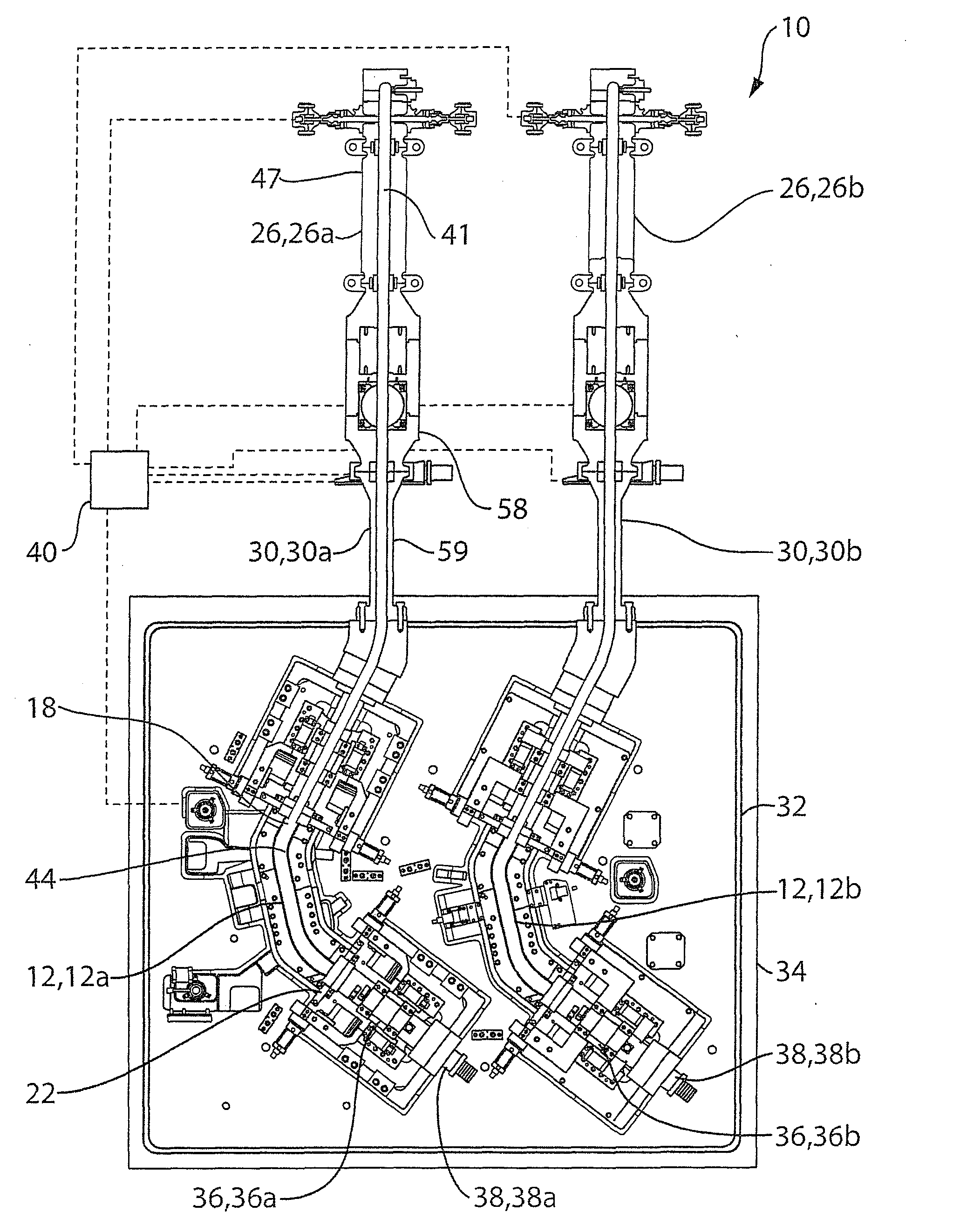
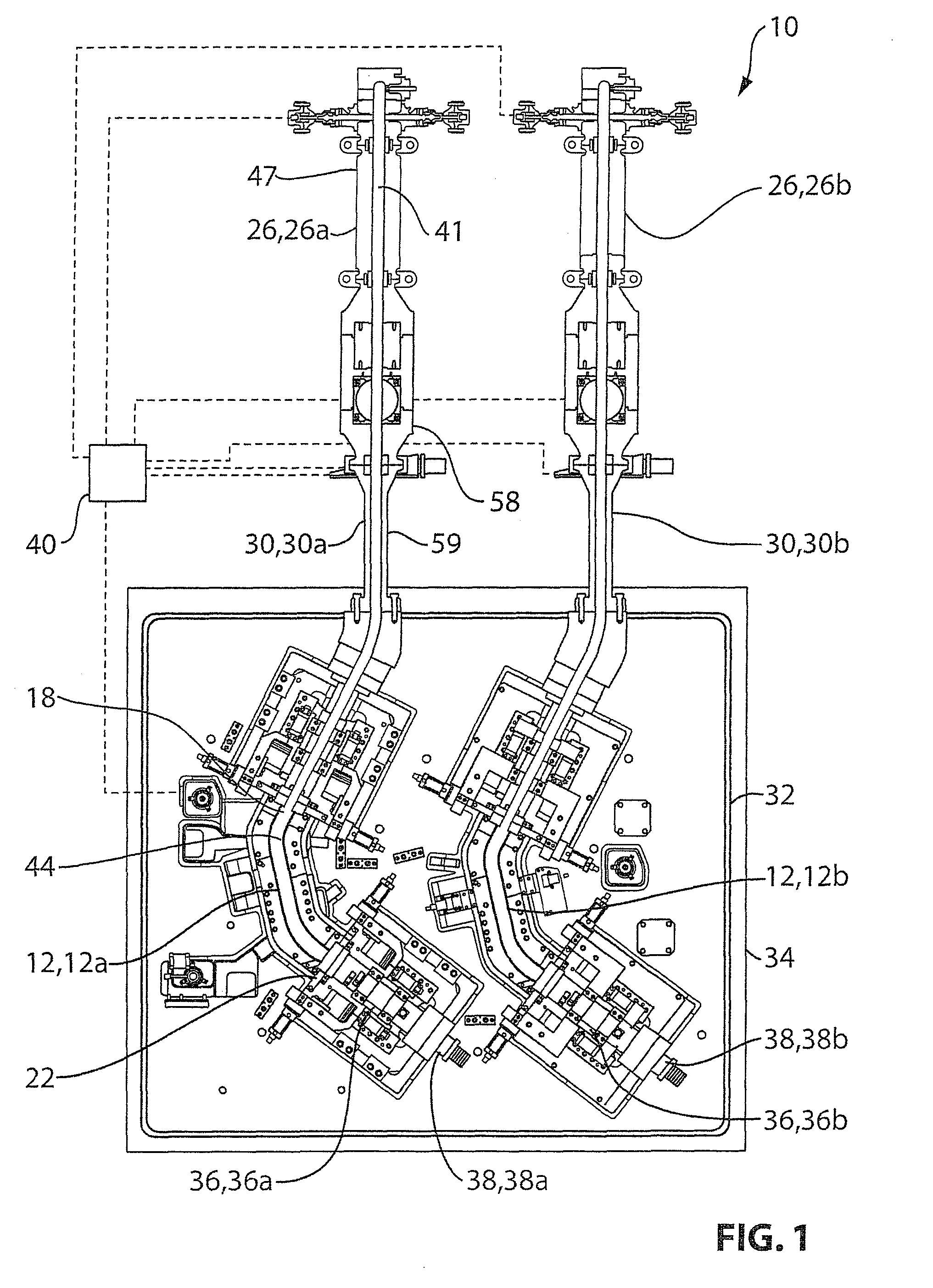
[0088]FIG. 1 shows an apparatus 10 for modifying a work piece 12 in accordance with a preferred embodiment of the invention. The apparatus 10 uses fluid pressure generated by an explosion (resulting from igniting combustibles shown at 47) to modify the work piece 12. In the preferred embodiment the apparatus 10 is configured to generate a shock wave 42 (FIG. 3) from the explosion and the pressure from the shock wave modifies the work piece 12, as discussed in greater detail below. However, the apparatus 10 may also be operated to modify the work piece 12 even if the explosion does not generate a shock wave, as discussed in greater detail below.

[0089]The apparatus 10 may perform different types of operation on the work piece 12 to modify the work piece 12 in one or more different ways...


PUM

PropertyMeasurementUnit
speedaaaaaaaaaa
speedaaaaaaaaaa
pressure Pswaaaaaaaaaa

Abstract

An explosion forming apparatus (10) that preferably utilizes a shock wave (42) directed along a work piece (12) to progressively conform the work piece to a contour die cavity (44).

Description

CROSS-REFERENCE TO RELATED APPLICATIONS[0001]This application claims the benefit of U.S. Provisional Application No. 61 / 049,021 filed Apr. 30, 2008. This application is also a continuation-in-part of U.S. application Ser. No. 12 / 447,727 filed Mar. 30, 2010 and entitled “Method and Mould Arrangement for Explosion Forming”, which is a national phase entry of PCT Application No. EP07 / 010,966 filed Dec. 13, 2007, which claimed priority to DE Serial No. 102007007330.7 filed Feb. 14, 2007.FIELD OF INVENTION[0002]The invention relates to systems for modifying parts using a pressurized fluid and more particularly to systems for modifying parts using a pressurized working fluid wherein pressurization of the working fluid is achieved by means of an explosion.BACKGROUND OF INVENTION[0003]Some types of pressure forming systems are explosion forming systems that use an explosion to generate pressure to form a work piece in a die cavity. Generally speaking, proposed systems for this purpose suffe...

Claims


Application Information

Patent Timeline
Patent Type & Authority Patents(United States)
IPC IPC(8): B21D26/02
CPCB21D26/08
Inventor ZAK, ALEXANDERKOTAGIRI, SEETARAMA S.HORTON, FRANK A.
Owner MAGNA INTERNATIONAL INC
Why Eureka
Try Eureka