Tracking system with scattering effect utilization, in particular with star effect and/or cross effect utilization

a tracking system and scattering effect technology, applied in the field of tracking systems, can solve the problems of significant errors, inability to tolerate one pixel accuracy errors, and substantial dependence on position determining accuracy

Inactive Publication Date: 2013-05-21
BRAINLAB
View PDF33 Cites 26 Cited by
  • Summary
  • Abstract
  • Description
  • Claims
  • Application Information

AI Technical Summary

Benefits of technology

[0019]The invention provides an image generating device used with an optical tracking system, such as a medical tracking system, or the like. The image generating device can be used to determine a position of a recorded image point, and can include a light scattering effect generating means. The light scattering effect generating means can generate a fuzzy image (as opposed to the conventional approach of enlarging the markers and / or increasing sensor resolution). Through the directed and defined scattering of marker light, a greater number of pixels on a sensor can be exposed, thus providing a spatially larger amount of information on the image sensor 2. Further, when light scattering effects are generated, brightness gradients are created (e.g., the image point is projected most brightly at the location where it actually is located and the brightness abates with distance from the image point's location). This provides a gradient that can be used when ascertaining the precise position of the image point. Thus, image point determination can be more precise, even though the image as a whole is actually fuzzier due to the light scattering effect.
[0023]With the above embodiments, a particular advantage arises as compared to targeted, diffuse defocussing, namely that by configuring the light scattering effect generating means, it is possible to predetermine the angles at which the cross and / or star pattern are going to be generated. With such prior known angles, it can be much simpler to detect and ascertain the intersection points. As a result, it also can be much simpler to ascertain the image points themselves, since only the brightest arrangement parallel to the star beams, which forms a line of “crosshairs”, need be ascertained. The projection of the image point (e.g., the marker) then can be said to be situated at the intersection point.
[0033]In another embodiment, the star and / or cross effects can be generated in at least a number of directions that exceeds the number of image points to be positionally ascertained by one. Using this configuration, an image point can be reliably ascertained where the highest number of effect lines intersect.

Problems solved by technology

Conventional tracking systems, which use camera systems having a predetermined image resolution, have the disadvantage that their position determining accuracy is substantially dependent on the resolution of the image generating devices.
Thus, in the case of small markers or image points having a size less than one pixel 4, a significant error can arise.
In the case of medical tracking systems or other tracking systems, which in many cases depend on accuracies of fractions of millimeters, an accuracy error of one pixel typically cannot be tolerated.
While the size of image points could be increased simply by using larger markers, larger markers would incur significant disadvantages related to handling, cost and weight of the markers.
All of these assumptions and restrictions incur disadvantages for conventional tracking systems.
However, very high resolution image generating devices are also very expensive and, therefore, significantly increase costs.
Also, some of the above problems cannot be solved simply by using exceedingly high resolution image generating devices.
For example, when image points are not completely visible, e.g., in the case of tarnished markers, higher resolution image generating devices offer little or no benefit.
Another disadvantage is that high resolution sensors usually have a significantly smaller pixel area and, therefore, are less sensitive.
The lower sensitivity of such sensors can result in potentially long exposure times and, therefore, are problematic when objects are moved.

Method used


Image

  • Tracking system with scattering effect utilization, in particular with star effect and/or cross effect utilization
  • Tracking system with scattering effect utilization, in particular with star effect and/or cross effect utilization
  • Tracking system with scattering effect utilization, in particular with star effect and/or cross effect utilization

Examples


Embodiment Construction

[0045]The present invention can be used within the framework of image-guided, navigation-assisted medical treatment. In such treatment, a position of a patient, a medical instrument and / or a treatment apparatus can be detected with the aid of markers and a camera system (tracking system), thereby enabling image-assisted surgery.

[0046]The invention has numerous advantages, including lower overall system costs, extremely small and light markers, simplified marker detection procedures, increased accuracy, and robust / reliable marker detection.

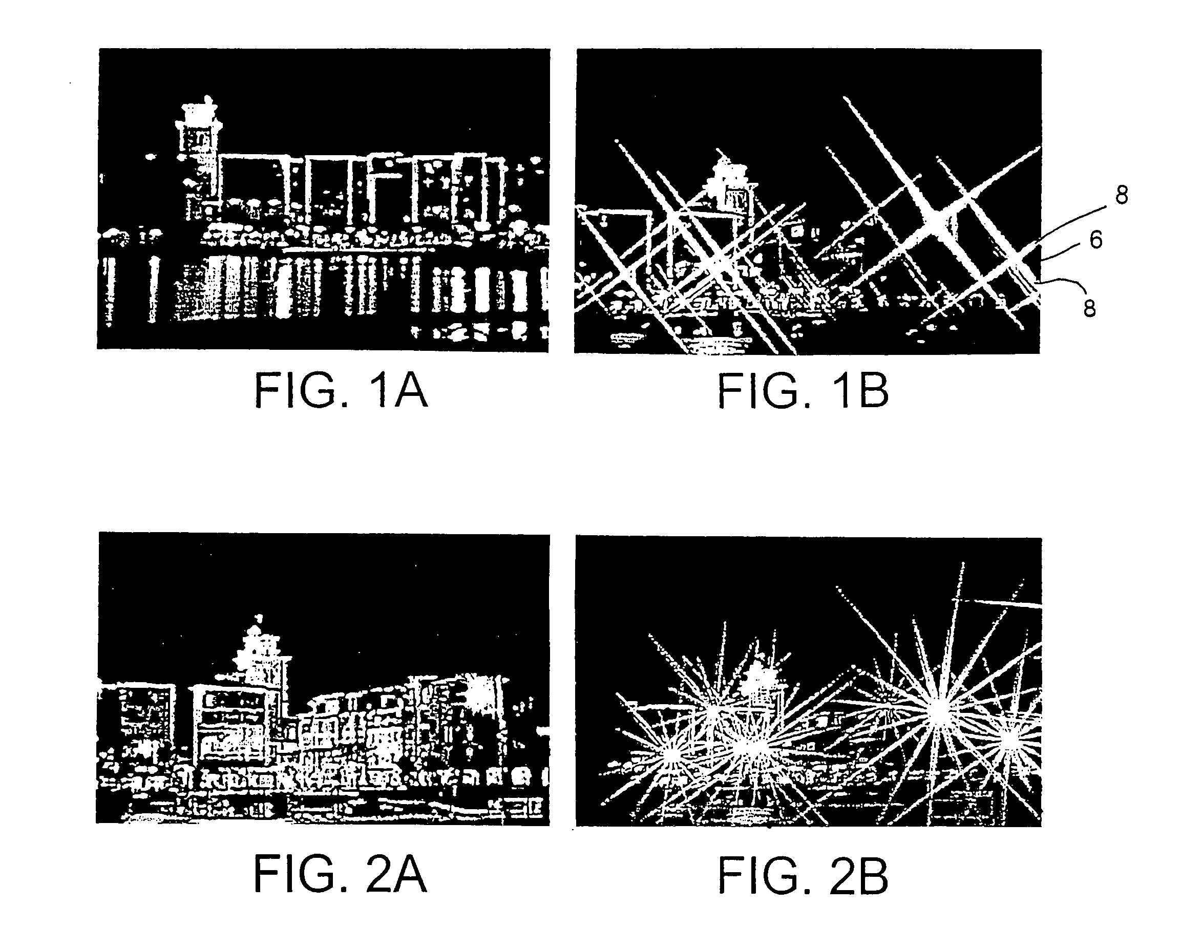
[0047]Light scattering effects such as, for example, star and / or cross effects, are shown in FIGS. 1A, 1B, 2A and 2B. The contrasted images show the effect of a star and / or cross filter in images with a number of bright image points (spotlights). As can be seen, using such an effect on the spotlights results in a cross pattern (FIG. 1B) or a star pattern (FIG. 2B), depending on the effect arrangement. The intersection point 6 of the perpendicular b...


PUM


Abstract

An image generating device for an optical, in particular medical tracking system, for determining the position of a recorded image point, includes a light scattering effect generating device, in particular a star and / or cross effect generating device. The invention further provides a tracking system including such an image generating device and to a method for determining the position of a recorded image point using an optical, in particular medical tracking system, in which: an image is generated using an image generating device; a light scattering effect, in particular a star and / or cross effect, is generated on the image for predetermined image points; and in which the position of an image point is ascertained on the basis of the light scattering pattern projected on the image, in particular on the basis of the star and / or cross effect lines and / or their intersection points.

Description

RELATED APPLICATION DATA[0001]This application claims priority of U.S. Provisional Application No. 60 / 618,855 filed on Oct. 14, 2004, which is incorporated herein by reference in its entirety.FIELD OF THE INVENTION[0002]The invention relates generally to tracking systems and, more particularly, to an image generating system, apparatus and method for use with an optical tracking system, such as a medical tracking system or the like, for determining a position of a recorded image point.BACKGROUND OF THE INVENTION[0003]Conventional optical tracking systems and their image generating devices generally include a pair of cameras that record individual image points. These image points, which typically comprise positional markers and / or natural landmarks, are used to detect information on a position (e.g., the spatial position of the image points) from a stereoscopic image obtained from the cameras. Thus, there are existing systems that include an image processing unit within the camera sys...

Claims


Application Information

Patent Timeline
Patent Type & Authority Patents(United States)
IPC IPC(8): H04N5/225H03K19/096A61B8/00
CPCA61B5/06A61B19/52A61B19/5244A61B2017/00411A61B2019/5255A61B2019/5265A61B2019/5437A61B2019/5445A61B5/064A61B34/20A61B90/36A61B2034/2055A61B2034/2065A61B2090/3937A61B2090/3945
Inventor GOLDBACH, GUNTER
Owner BRAINLAB
Why Eureka
Try Eureka