
Flat thin dynamic speaker

a dynamic speaker and speaker body technology, applied in the direction of deaf-aid sets, electrical transducers, transducer details, etc., can solve the problems of reducing the total available displacement along the z-axis, reducing the surface area available, and difficult to design well-performing speakers in other shapes than ellipses and circles, etc., to achieve high output, not increased overall thickness of the speaker body, and high sound quality

Active Publication Date: 2013-05-21
D & J
View PDF2 Cites 9 Cited by
  • Summary
  • Abstract
  • Description
  • Claims
  • Application Information

AI Technical Summary

Benefits of technology

The present invention is a slim and quadrangular speaker assembly that has a high output and is capable of a high quality of sound effect comparable to a conventional eclipse or spherical shaped speaker. The assemble comprises a frame, a motor, a suspension means, and a radiating means. The overall thickness of the speaker assembly is not increased by the suspension means, the optimized construction of the radiating means is not limited by the suspension means, and the radiating area of the radiating means is not reduced by the provision of surround. The speaker assembly is also optimized in terms of materials limitation for the suspension means and the radiating means, and the surface area of the radiating means is maximized, independent on the size of the suspension means and the surround. Additionally, the speaker assembly has a dual side voice-coil actuation to the radiation means.

Problems solved by technology

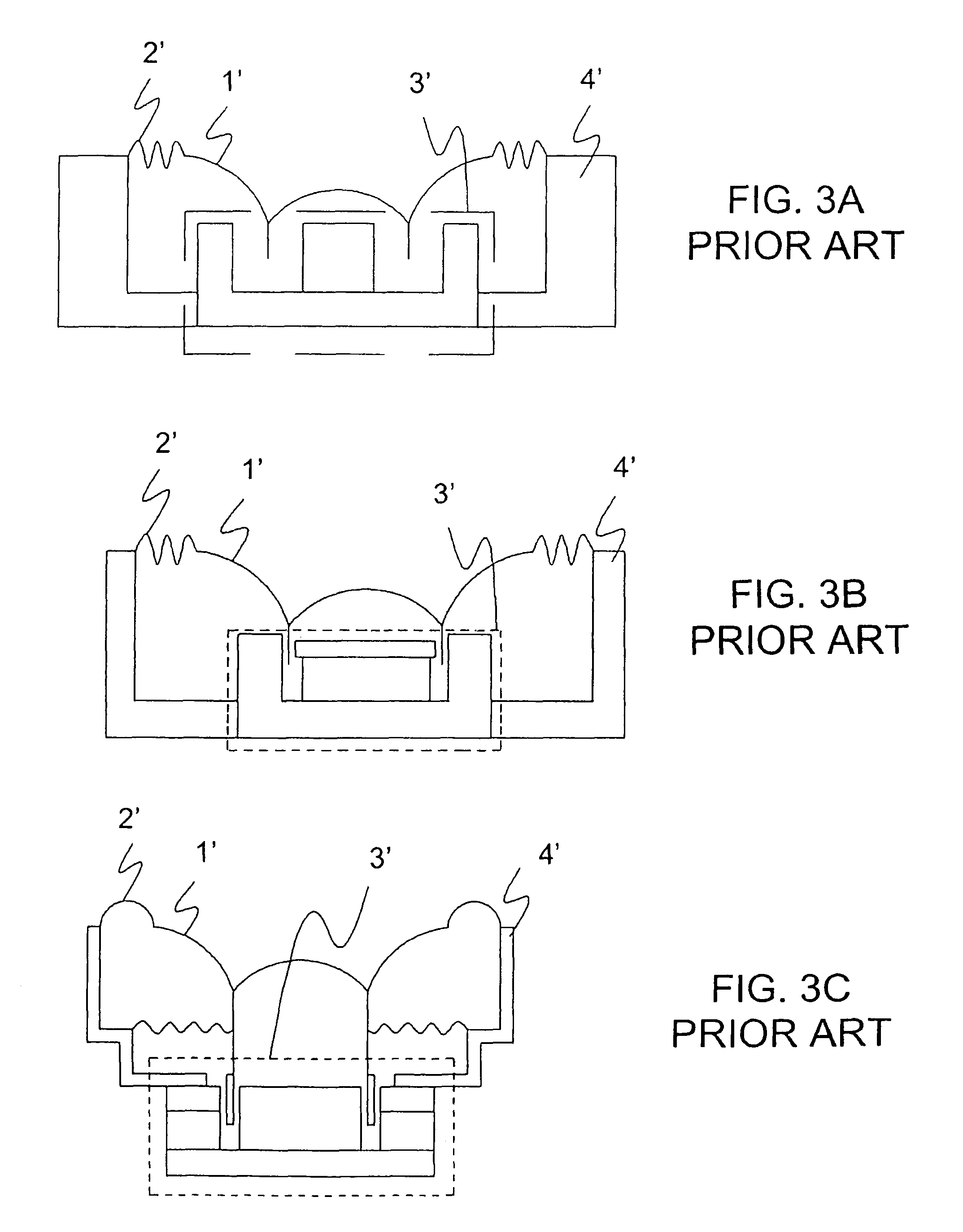
The physical size of the components necessary for a particular application constrains the range of sizes of the speaker assembly, and the conventional arrangement of components makes it difficult to design well performing speakers in shapes other than ellipses and circles.
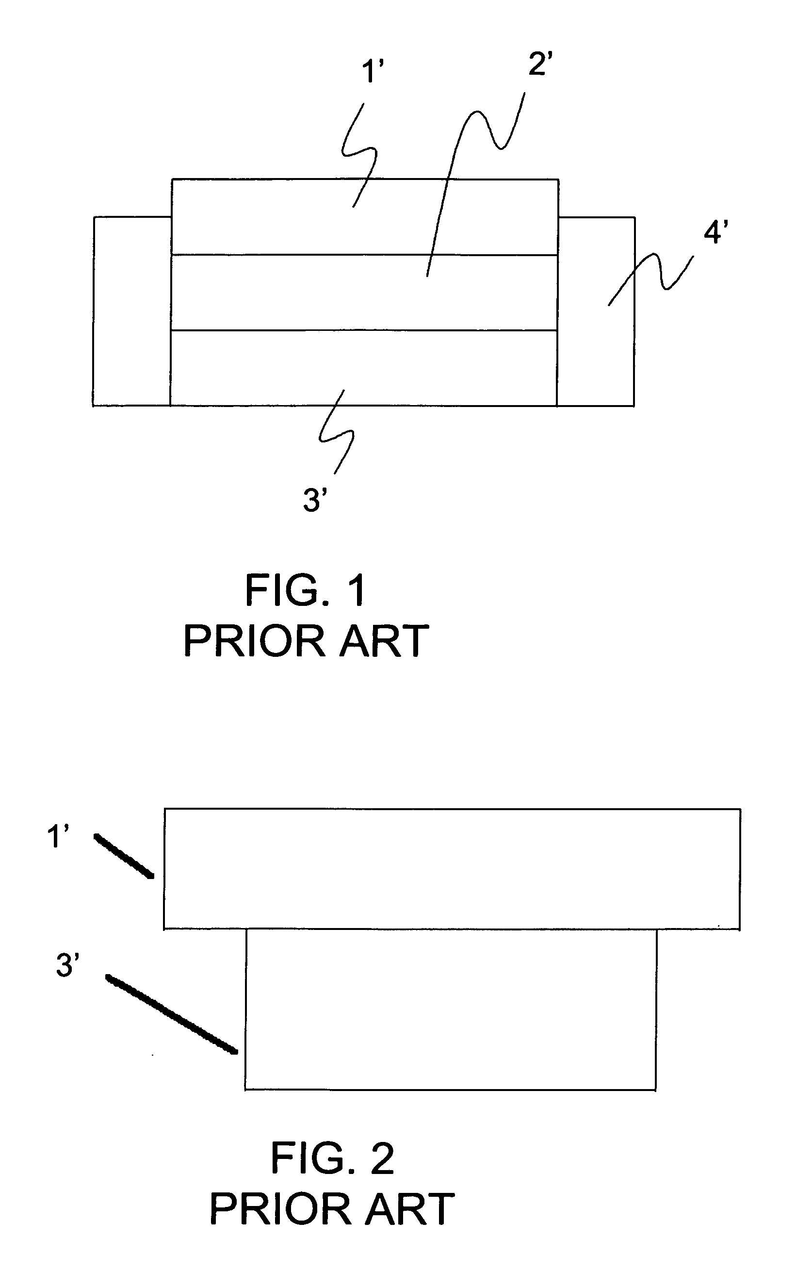
This approach allows for a lower profile, but it has several disadvantages that hurt performance.
The conventional thin speaker approach also trades away some of the available surface area available for a given size radiating means to radiate power to make room for the flexible suspension means and also reduces the total available displacement along the Z-axis for lacking additional suspension.
The reduced surface area available further reduces the maximum achievable acoustical output power.
The conventional thin speaker approach trades away performance to reduce thickness and is unsatisfactory.

Method used


Image

  • Flat thin dynamic speaker
  • Flat thin dynamic speaker
  • Flat thin dynamic speaker

Examples


Embodiment Construction

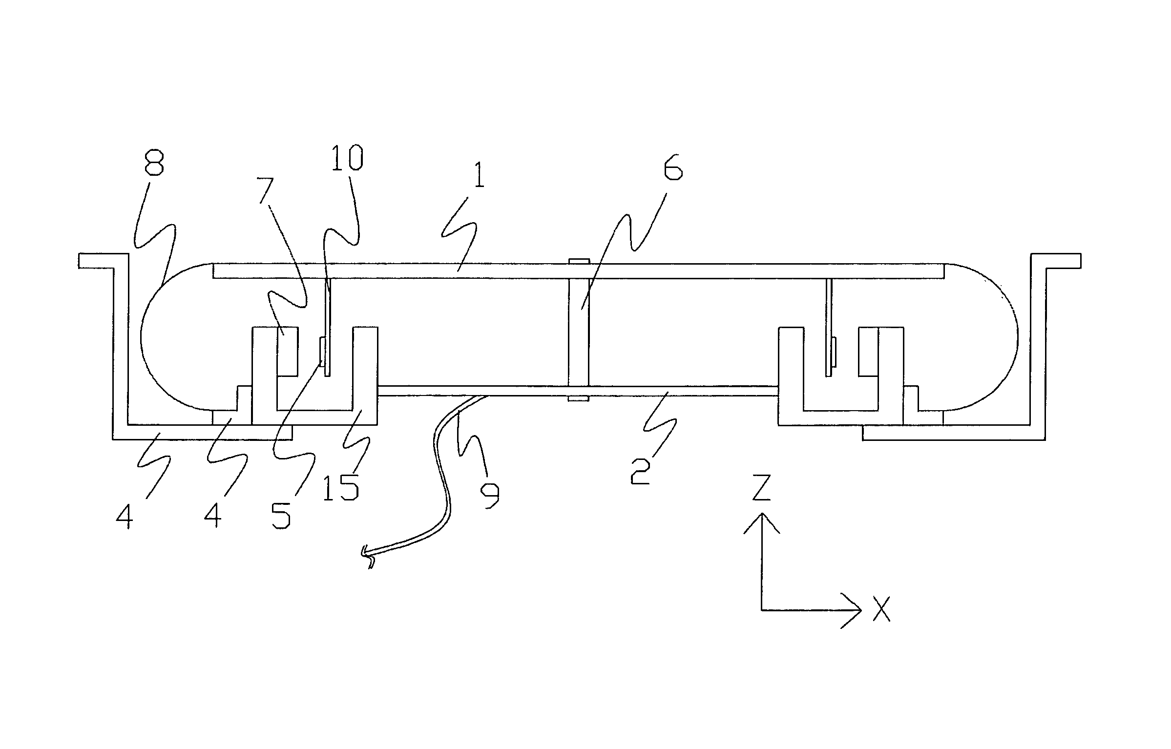
[0059]Referring to FIGS. 4 to 23, a speaker assembly according to a preferred embodiment of the present invention is illustrated.

[0060]Referring to FIG. 4, which is a schematic representation of the preferred embodiment of the present invention, the motor 3 is positioned at the periphery of the speaker assembly, making it possible for the flexible suspension means 2 to be mounted in the same plane as the motor, thus reducing the minimum achievable height of the stack of components needed for a given application and level of performance.

[0061]FIG. 5 shows a cross-section of the simplified example. The thin flat speaker may be of many different sizes and shapes in the X-Y plane, such as eclipse, rectangle, triangular, and square, as long as the shape allows the general arrangement of components shown in FIG. 5.

[0062]It can be seen from FIG. 5 that the radiating means 1, which is a radiating unit, is mounted to the magnetic yoke 15 by means of a rigid connecting posts 6 and a flexible ...


PUM


Abstract

A flat thin dynamic speaker which includes a motor unit, a suspension unit, a radiating unit and a frame arranged in such a manner that the motor unit and the suspension unit are at the same plane while the radiating unit is on top of the motor unit such that the thickness of the speaker assembly is reduced while the performance of the speaker assembly is maintained or even improved. Also, the speaker can be made into a quadrangular, polygon or a spherical structure. The speaker further has a surround at a level lower than the radiating unit without utilizing the radiating surface of the radiating unit such as a maximized radiating surface is provided, and includes a dual side voice-coil actuation to the radiator unit, thereby providing a slim and flat speaker assembly with high power output.

Description

CROSS REFERENCE OF RELATED APPLICATION[0001]This is a non-provisional application that claims the benefit of priority under 35 U.S.C. §119 to a provisional application, application No. 61 / 299,937, filed Jan. 30, 2010.BACKGROUND OF THE PRESENT INVENTION[0002]1. Field of Invention[0003]The present invention relates to a flat thin dynamic speaker, and more particularly to a flat thin dynamic speaker with a novel arrangement of components that yields a large radiating surface area and high output levels compared to conventional dynamic speakers of the same thickness and footprint by having the magnetic circuit at the same level as the suspension means.[0004]2. Description of Related Arts[0005]For many products containing speakers such as flat screen television receivers, cell phones, and portable computers, it is desirable to use speakers as flat and thin as possible and often in shapes other than round or ellipse so as not to limit the designer's options for the design and appearance o...

Claims


Application Information

Patent Timeline
Patent Type & Authority Patents(United States)
IPC IPC(8): H04R25/00
CPCH04R9/06H04R1/00H04R9/043H04R9/025H04R9/045H04R1/2834
Inventor CHU, WALTER KA WAI
Owner D & J
Learn More