
Methods and apparatus for power-equalized optical frequency comb generation

a technology of power-equalization and optical frequency comb, which is applied in the direction of multiplex communication, instruments, optical elements, etc., can solve the problems of affecting the output of the mll source, affecting the coherence and frequency stability of the optical frequency comb, and imposing the most severe stability requirement, etc., to achieve the effect of enhancing the total number of second optical waves, reducing the noise level of the optical frequency comb, and enhancing the coherence and frequency stability

Active Publication Date: 2013-05-21
ROSHMERE INC
View PDF7 Cites 19 Cited by
  • Summary
  • Abstract
  • Description
  • Claims
  • Application Information

AI Technical Summary

Benefits of technology

This patent describes a new optical device that generates a frequency comb. The device includes an optical source with two input optical waves that are mixed to create a plurality of optical waves with different frequencies. One of the waves is compressed to reduce its bandwidth, while another wave is designed to increase the number of output waves. This results in an increase in the overall power and stability of the comb. The device also reduces the noise level and improves the coherence and accuracy of its frequency combs. Overall, this technology allows for the creation of more powerful and precise frequency combs, which can be useful in a variety of applications.

Problems solved by technology

The use of an MLL source for frequency comb generation necessarily introduces performance limitations.
The most severe limit is imposed by the stability requirement placed on the MLL cavity.
In the case when the MLL cavity is not sufficiently stabilized, its output is characterized by temporal and frequency uncertainty.
Consequently, the tolerance required to control such cavity length decreases until it reaches a physical scale that cannot be physically realized.

Method used


Image

  • Methods and apparatus for power-equalized optical frequency comb generation
  • Methods and apparatus for power-equalized optical frequency comb generation
  • Methods and apparatus for power-equalized optical frequency comb generation

Examples


Embodiment Construction

[0043]Embodiments of the invention provide apparatuses and methods for generation of wideband, spectrally equalized frequency combs that are seeded by CW tones. These embodiments of the invention afford improved performance characteristics of the generated frequency combs, which have a wide range of applications.

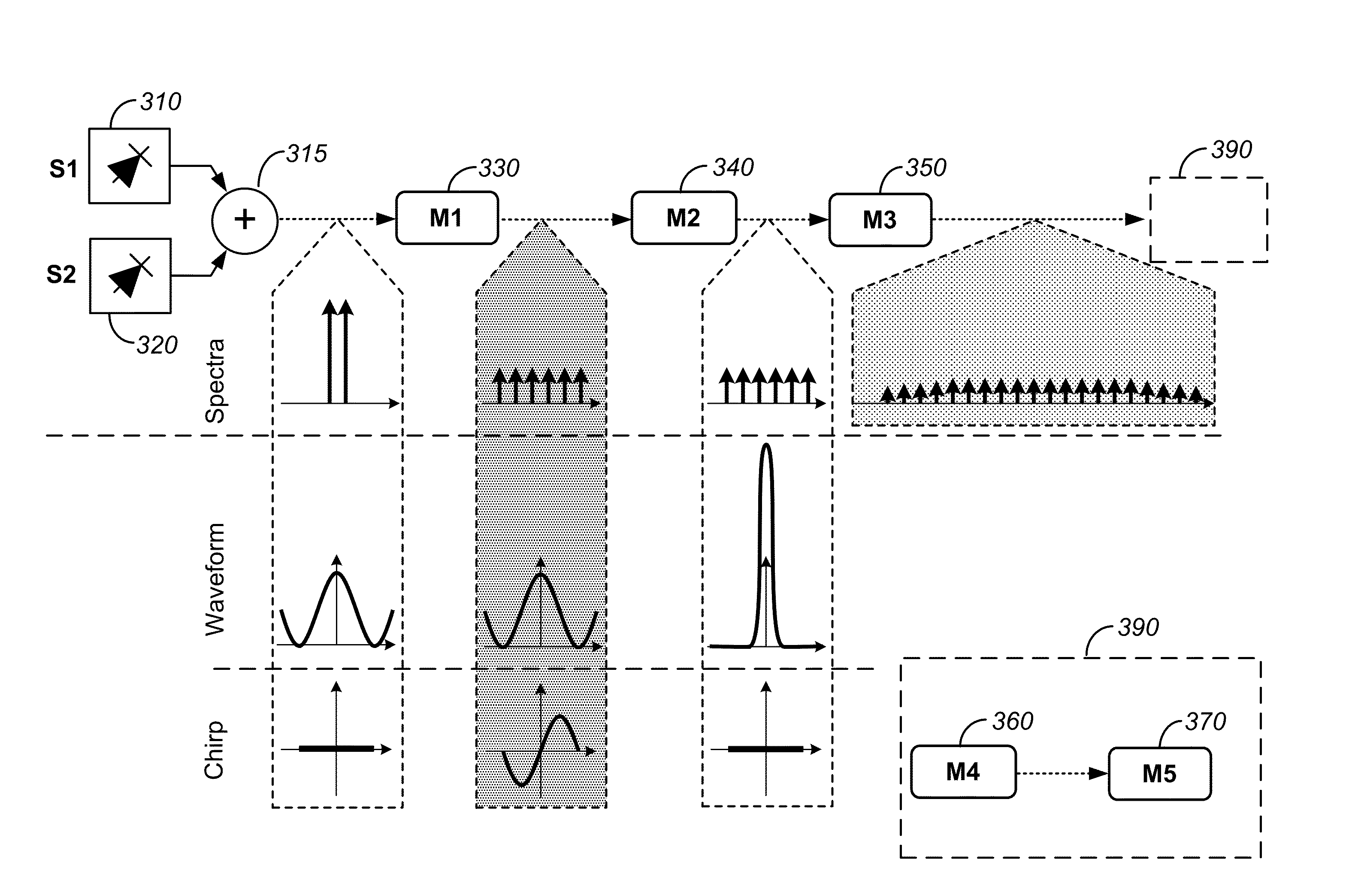
[0044]In an alternative to the conventional approach, a frequency comb synthesis can be accomplished without an MLL. Indeed, if a continuous-wave (CW) source can be used to seed frequency comb generation, the inherent limits associated with an MLL or any other pulsed source can be circumvented. Two CW sources (tones) are used in some embodiments to seed an optical mixer and to generate new frequency tones. In an efficient mixing process, a large number of spectrally equidistant tones can be generated, thus creating a wideband frequency comb. Such generation, while circumventing instabilities inherent to MLL cavities utilizes a mixing process to generate a large number of new...


PUM


Abstract

An optical device for generating a frequency comb includes an optical source and a first waveguide comprising a nonlinear optical medium operable to mix at least two input optical waves to generate a plurality of first optical waves. The optical device also includes a second waveguide concatenated to the first waveguide and characterized by a first dispersion characteristics and operable to compress the waveforms of the plurality of first optical waves and to reduce a frequency chirp introduced by the first waveguide. The optical device additionally includes a third waveguide concatenated to the second waveguide. The third waveguide comprises a nonlinear optical medium and is operable to mix the plurality of first optical waves to generate a plurality of second optical waves and to increase a total number of second optical waves with respect to a total number of first optical waves.

Description

CROSS-REFERENCES TO RELATED APPLICATIONS[0001]This application claims priority to U.S. Provisional Patent Application No. 61 / 700,807, filed on Sep. 13, 2012, entitled “Methods and Apparatus for Power-Equalized Optical Frequency Comb Generation,” the disclosure of which is hereby incorporated by reference in its entirety for all purposes.BACKGROUND OF THE INVENTION[0002]An optical or radio-frequency (RF) source is commonly referred to as a frequency comb when its spectral representation is given by multiple, equidistantly spaced frequency tones. Various mechanisms can be used to generate a frequency comb; these are often classified with respect to their spectral bandwidth, frequency stability, spectral tone purity (i.e., signal-to-noise ratio or SNR), coherence and power. Frequency combs can be used to establish a spectral reference that can be used to relate the position of a spectral absorption or emission profile in applications such as in precision ranging, spectroscopy, sensing,...

Claims


Application Information

Patent Timeline
Patent Type & Authority Patents(United States)
IPC IPC(8): G02B6/00
CPCG02F1/353G02F1/383G02F1/39G02B6/00G02B6/02247G02F2203/56G02F2201/16G02F2203/26
Inventor KUO, PING PIUMYSLIVETS, YAUHENI
Owner ROSHMERE INC
Features
  • Generate Ideas
  • Intellectual Property
  • Life Sciences
  • Materials
  • Tech Scout
  • Unparalleled Data Quality
  • Higher Quality Content
  • 60% Fewer Hallucinations
Learn More