Data and event synchronization across distributed user interface modules

a distributed user interface and event synchronization technology, applied in the field of computer networks, can solve the problems of slowing down, insufficient software solutions, and easy desynchronization of user control of user interfaces

Active Publication Date: 2013-05-21
DECISION LENS
View PDF47 Cites 54 Cited by
  • Summary
  • Abstract
  • Description
  • Claims
  • Application Information

AI Technical Summary

Problems solved by technology

Nevertheless, existing software solutions can be inadequate when data is actively modified and / or when users are actively switching between application modules, and when user interfaces should be coordinated.
Interactive data presentation and / or user control of user interfaces can easily become de-synchronized, or can slow down due to untimely attempts to synchronize activity.
So-called decision support systems (DSS), that help users compile information and structure a decision model to identify and solve problems and make decisions, present a further challenge.
Typically voting on a decision in a DSS can be remote, but a DSS typically does not have application sharing due to the data-intensive nature of use.

Method used


Image

  • Data and event synchronization across distributed user interface modules
  • Data and event synchronization across distributed user interface modules
  • Data and event synchronization across distributed user interface modules

Examples


example embodiment 1

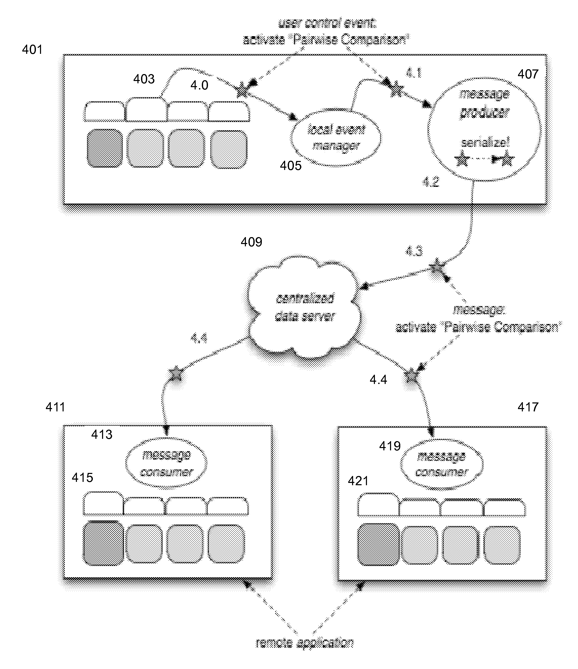
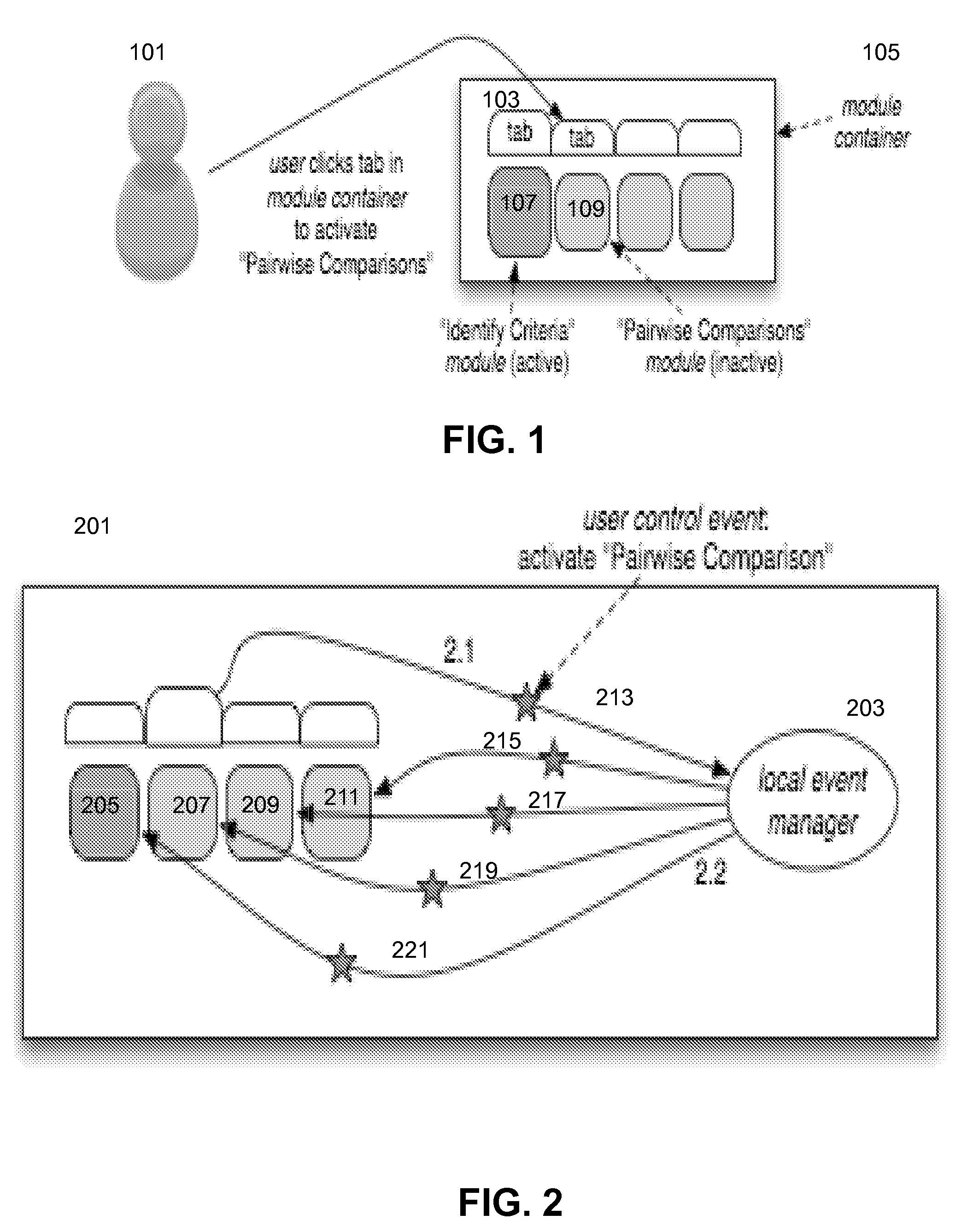
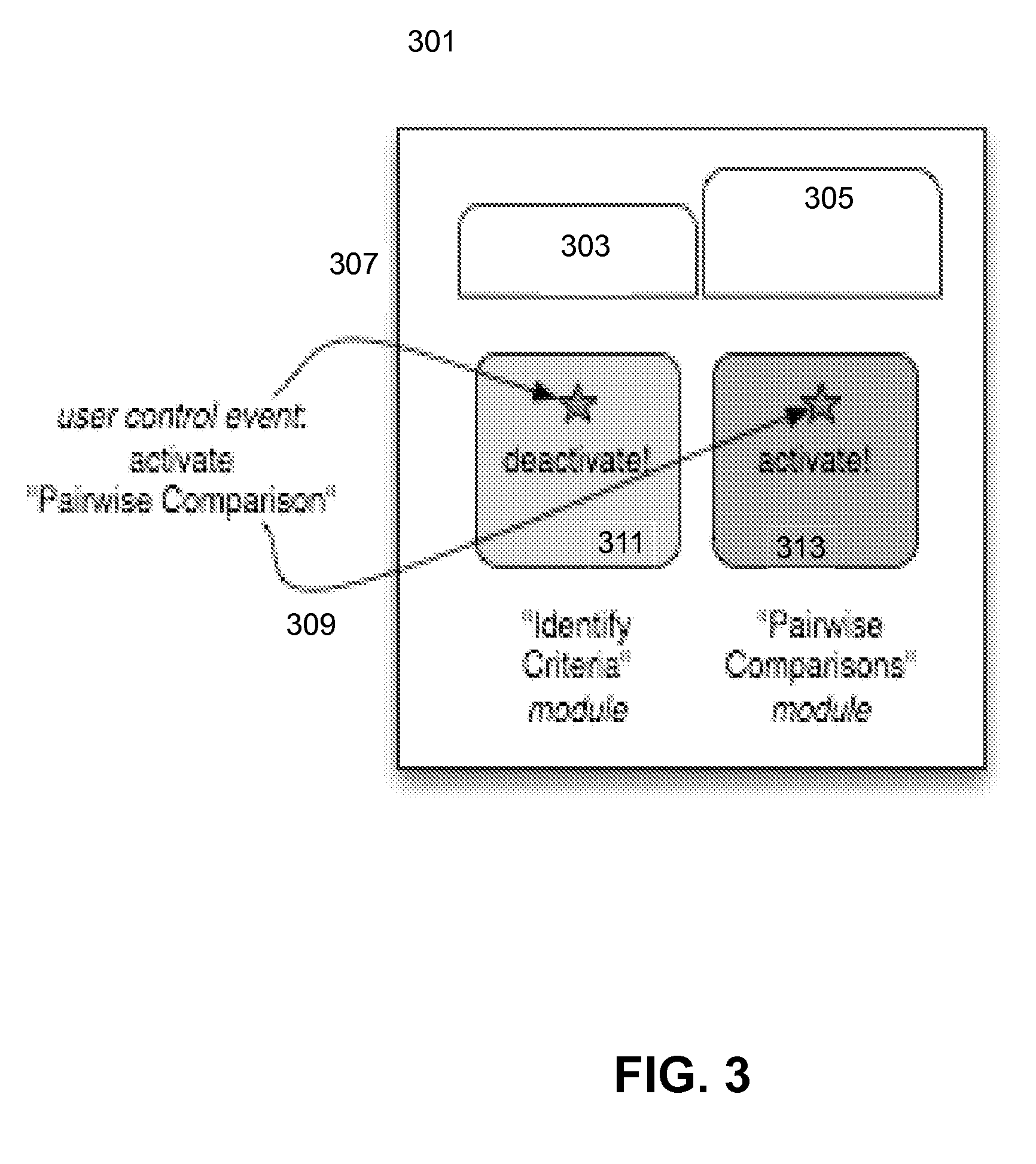
[0105]The following example describes one possible embodiment, herein within a web-distributed application, for example, a decision support system sometimes referred to hereafter as “DL3.” Familiarity is assumed with decision support software available from Decision Lens, Inc. In this example, a user intends to add additional criteria to the criteria tree and to adjust the available pairwise criteria comparisons accordingly. This embodiment is simple, to illustrate basic concepts.

[0106]The modules in this embodiment include:[0107]“Identify Criteria”—This module encapsulates the user interface controls and data visualization components related to building a criterion tree. This module displays the current criteria tree, as retrieved from the centralized data server, and provides controls for adding and removing criteria to and from the tree.[0108]“Pairwise Comparison”—This module encapsulates the user interface controls and data visualization components related to voting on pairwise ...

example embodiment 2

[0227]Referring now to FIG. 19, a block diagram illustrating portions of a second embodiment of a computer constructed for use in being synchronized with plural applications will be discussed and described. The second embodiment has the same elements illustrated as the computer in FIG. 13, except that reference numbers begin with “19 . . . ” instead of “13 . . . ” (for example, computer 1301 is computer 1901). In FIG. 19, a detailed illustration of contents of 1st local module 1917 and 2nd local module 1925 are not illustrated due to lack of space. The elements which were discussed in connection with FIG. 13 may be omitted from the following discussion so as to avoid obscuring the discussion.

[0228]In comparison to FIG. 13, it will be noted that FIG. 19 shows a 1st application 1913 (illustrated in FIG. 13; parts in this figure are omitted from the illustration) and additionally shows 2nd application 1973. The 2nd application 1973 can include, for example, a 1st module container 1975,...


PUM


Abstract

A computer includes, among other things, local modules contained within a module container of a same application; a message producer unit to communicate with a data server over the i / o interface; a message consumer unit configured to communicate with the data server over the i / o interface; and a local event manager unit. There is a pre-defined sequence of processing events between the local event manager unit, the local modules within the same application of the same module container, remote modules, the message producer unit, and the message consumer unit.

Description

TECHNICAL FIELD[0001]The technology relates in general to computer networks, and more specifically to synchronizing distributed independent application modules, optionally on remote computers, for performance of a coordinated user experience.TECHNICAL BACKGROUND[0002]Web-based application modules may be used to conduct live meetings, training, education, and / or presentations via a computer network, such as the Internet. In some web-based application techniques, each participant in the meeting or the like sits at his or her own computer and is connected to other participants via the Internet. The web-based application can be, for example, a downloaded application executing on each of the users' computers or a remote application where the attendees access the meeting by clicking on a link distributed by a meeting invitation e-mail to enter the meeting.[0003]A feature that web-based collaboration applications sometimes offers is referred to as “screen sharing”, “desktop sharing”, or “a...

Claims


Application Information

Patent Timeline
Patent Type & Authority Patents(United States)
IPC IPC(8): G06F15/16
CPCG06Q10/10G06Q10/06
Inventor GAY, RYAN PATRICK
Owner DECISION LENS
Why Eureka
Try Eureka