

Systems and methods for melting scrap metal
a scrap metal and system technology, applied in the direction of process efficiency improvement, lighting and heating apparatus, furnaces, etc., can solve the problems of difficult removal, broken pump parts, and difficulty in breaking and maintaining, and achieve the effect of assisting in melting
- Summary
- Abstract
- Description
- Claims
- Application Information
AI Technical Summary
Benefits of technology
Problems solved by technology
Method used
Image

Examples
Embodiment Construction
[0001]This application claims priority to and incorporates by reference the disclosures of: U.S. Provisional Application No. 61 / 232,392 filed Aug. 7, 2009.
FIELD OF THE INVENTION
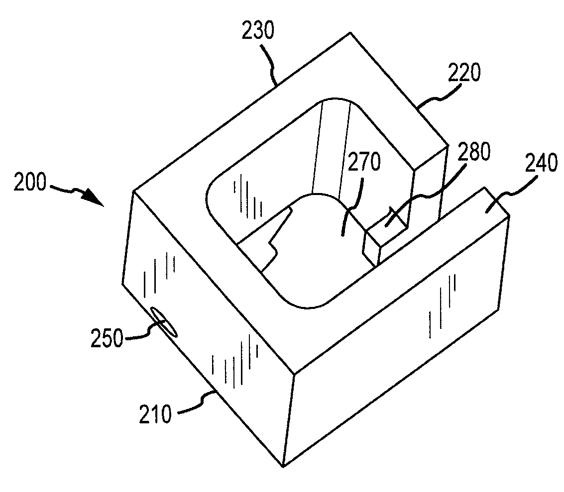
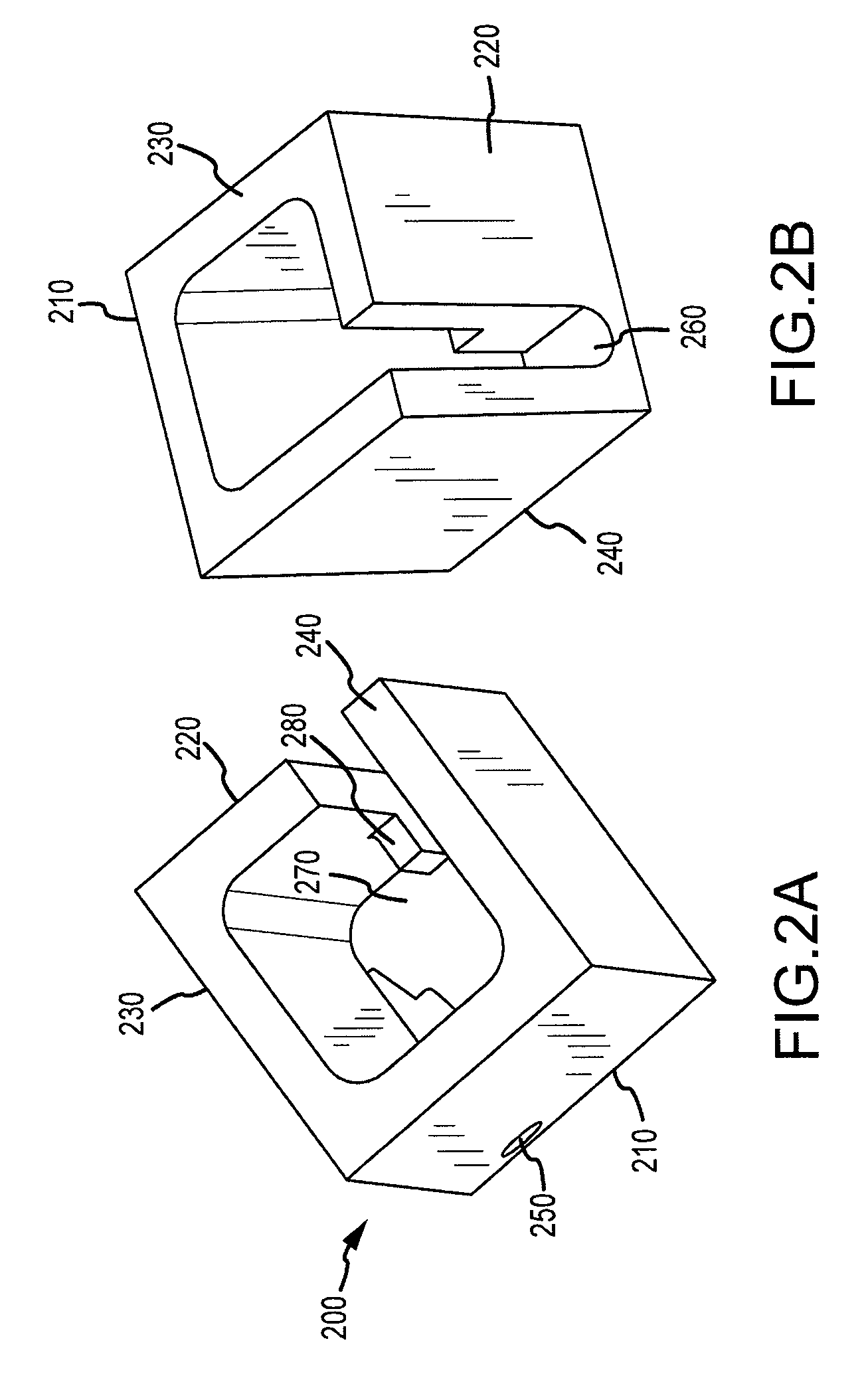
[0002]The invention relates to systems and methods for melting scrap metal. More particularly, the invention relates to systems and methods for melting scrap metal using a vessel comprising a directional flow member.
BACKGROUND OF THE INVENTION
[0003]As used herein, the term “molten metal” means any metal or combination of metals in liquid form, such as aluminum, copper, iron, zinc, and alloys thereof. The term “gas” means any gas or combination of gases, including argon, nitrogen, chlorine, fluorine, Freon, and helium, which may be released into molten metal.
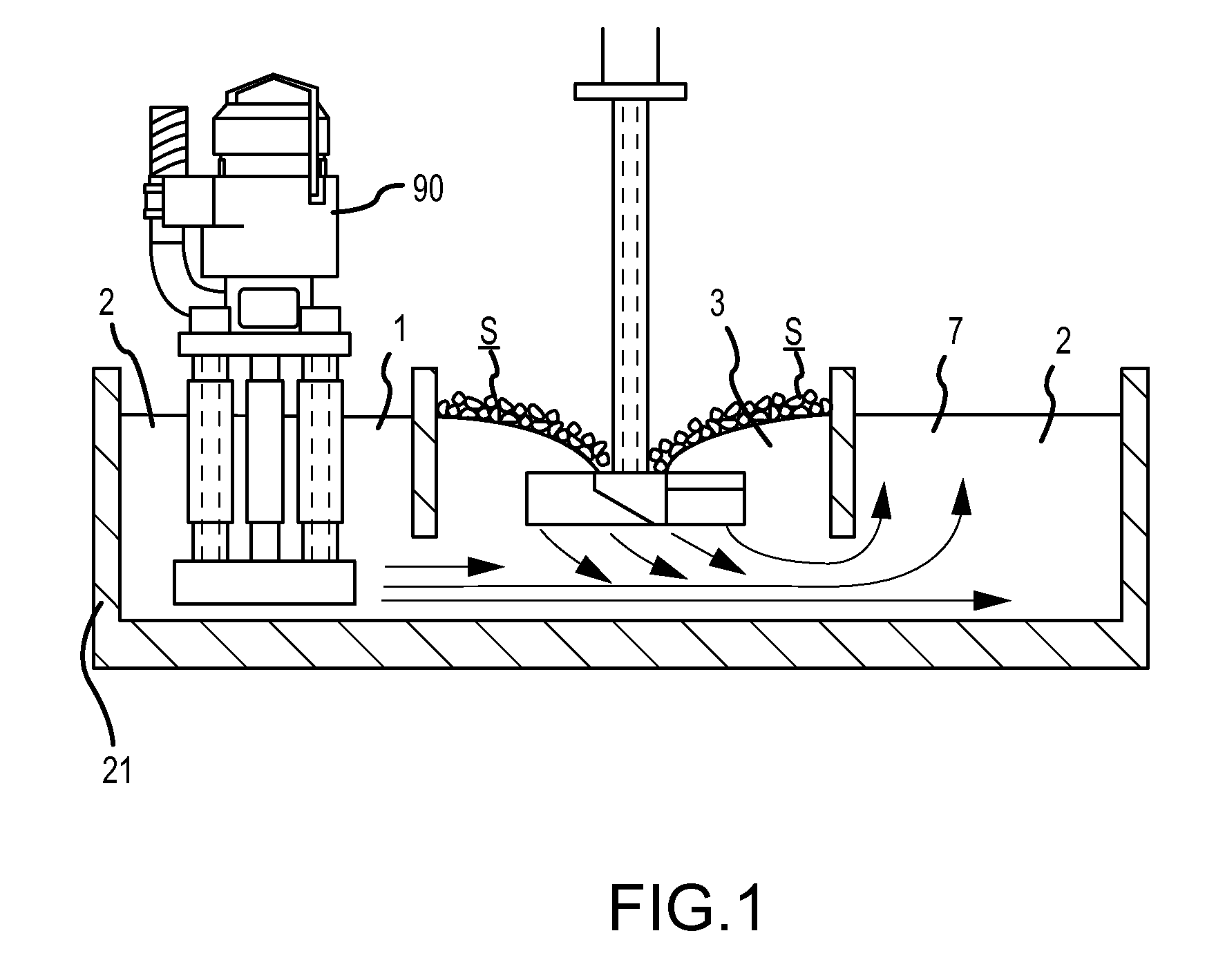
[0004]A reverbatory furnace is used to melt metal and retain the molten metal while the metal is in a molten state. The molten metal in the furnace is sometimes called the molten metal bath. Reverbatory furnaces usually include a chamber for retaining a mo...
PUM
| Property | Measurement | Unit |
|---|---|---|
| height | aaaaa | aaaaa |
| width | aaaaa | aaaaa |
| height | aaaaa | aaaaa |
Abstract
Description
Claims
Application Information