X-ray tomographic inspection system for the identification of specific target items

a tomographic inspection and target item technology, applied in tomography, applications, instruments, etc., can solve the problems of speed of known systems, incompatibility of swept beam scanners with conveyor systems, and high cost and time consumption of processes

Active Publication Date: 2013-05-28
RAPISCAN SYST INC (US)
View PDF398 Cites 67 Cited by
  • Summary
  • Abstract
  • Description
  • Claims
  • Application Information

AI Technical Summary

Problems solved by technology

However, because the electron source lies on the axis of rotation, such swept beam scanners are not compatible with conveyor systems which themselves pass close, and parallel, to the axis of rotation.
Such processes are expensive and time consuming.
Due to the slow speed of known systems, only a small fraction of baggage and cargo items can be screened in this way.

Method used


Image

  • X-ray tomographic inspection system for the identification of specific target items
  • X-ray tomographic inspection system for the identification of specific target items
  • X-ray tomographic inspection system for the identification of specific target items

Examples


embodiment three

Confirmatory Sensor X-Ray Backscatter Imaging

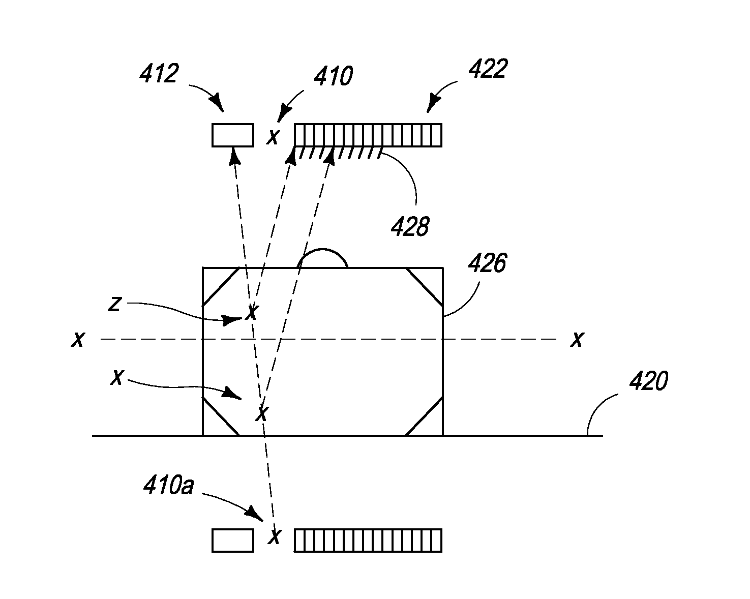
[0187]In another embodiment, the confirmatory sensor comprises an X-ray backscatter imaging system.

[0188]X-ray backscatter is produced when X-rays undergo a Compton interaction. Here, the scattered X-ray is left with less energy than it had before the collision, the difference in energy being delivered to an electron in the material under investigation. There is a good probability that the X-ray will be scattered back in the direction from which it came and this backscattered X-ray can be detected with one or more X-ray sensors located adjacent to the source of X-rays. The direction of the scattered X-rays is independent of the direction of the input beam and therefore there is only weak spatial correlation between the backscattered signal from a particular object and the backscatter signal detection signal.

[0189]It is therefore preferable to incorporate a collimator into the system, between the X-ray source and the object under investig...


PUM

PropertyMeasurementUnit
speedaaaaaaaaaa
angleaaaaaaaaaa
speedaaaaaaaaaa

Abstract

The present invention provides for an improved scanning process with a stationary X-ray source arranged to generate X-rays from a plurality of X-ray source positions around a scanning region, a first set of detectors arranged to detect X-rays transmitted through the scanning region, and at least one processor arranged to process outputs from the first set of detectors to generate tomographic image data. The X-ray screening system is used in combination with other screening technologies, such as NQR-based screening, X-ray diffraction based screening, X-ray back-scatter based screening, or Trace Detection based screening.

Description

CROSS-REFERENCE TO RELATED APPLICATIONS[0001]The present application relies on U.S. Patent Provisional Application No. 61 / 181,070 filed on May 26, 2009, for priority.[0002]The present application is also a continuation-in-part of U.S. Patent Application No. 12 / 485,897, filed on Jun. 16, 2009 now abandoned, which is a continuation of U.S. patent application Ser. No. 10 / 554,656, filed on Mar. 29, 2007, and now issued U.S. Pat. No. 7,564,939, which is a 371 national stage application of PCT / GB04 / 01729, filed on Apr. 23, 2004 and which, in turn, relies on Great Britain Application No. 0309387.9, filed on Apr. 25, 2003, for priority.[0003]The present application is also a continuation-in-part of U.S. patent application Ser. No. 12 / 371,853, filed on Feb. 16, 2009 now U.S. Pat. No. 7,903,789, which is a continuation of U.S. patent application Ser. No. 10 / 554,975, filed on Aug. 2, 2006, and now issued U.S. Pat. No. 7,512,215, which is a 371 national stage application of PCT / GB2004 / 01741, fi...

Claims


Application Information

Patent Timeline
Patent Type & Authority Patents(United States)
IPC IPC(8): G01N23/04
CPCG01N23/046H01J35/045G01V5/005G01N23/04A61B6/027A61B6/032A61B6/4035A61B6/4241A61B6/4488A61B6/482G01N2223/419A61B6/4028A61B6/505G21K1/025G01N23/203G01N24/084G01V5/0033
Inventor MORTON, EDWARD JAMES
Owner RAPISCAN SYST INC (US)
Why Eureka
Try Eureka