Method and apparatus for sawing lineal material to length

a lineal material and method technology, applied in the direction of metal sawing accessories, instruments, static/dynamic balance measurement, etc., can solve the problems of not preventing the operator from accidentally cycling the saw, not being able to operate, adding significant cost and complexity to the product, etc., to reduce or eliminate the disadvantages and shortcomings, keep the operator's hands a safe distance from the cutting area, and eliminate time and effort

Active Publication Date: 2013-06-04
TECHNOLOGY SERVICE CORPORATION
View PDF18 Cites 2 Cited by
  • Summary
  • Abstract
  • Description
  • Claims
  • Application Information

AI Technical Summary

Benefits of technology

[0009]In accordance with the present invention, the disclosed sawing system enhancement, and the method of operation thereof, substantially reduce or eliminates the disadvantages and shortcomings associated with the prior art techniques. According to one aspect of the invention, the two buttons that are monitored by the anti-tie down circuit are mounted on handrests positioned above the work area and on either side of the cutting line. These hand rests are mounted on linear bearings that allow them to slide horizontally in a plane parallel to the saw blade and to the saw table top and perpendicular to the saw back fence. The hand rests may be joined together or they may move independently depending on the embodiment of the invention. Either integrated into the design of the hand rests or mechanically connected to the hand rests are mechanical features that extend down toward the table top to within a short distance of its surface. These features will come in contact with the stock to be cut as the operator applies forward force to the hand rests causing them to slide toward the back fence of the saw. In this way the operator can crowd stock against the saw's back fence yet still operate the two-hand anti-tie down switches positioned to keep his hands a safe distance from the cutting area.
[0010]In accordance with another aspect of the invention, additional buttons can be positioned on the hand rests to perform functions such as controlling a digitally controlled positioning device attached to the saw to position the stock to obtain a desired cut length. As an example the hand rests might include a JOG button and a NEXT PART button. The operator could place his stock on a positioning table next to the saw; depress the JOG button on the hand rest assembly, thereby feeding the stock toward the saw. When the stock is in a position where the saw will make a proper trim cut, the operator would release the JOG button stopping the forward motion of the stock. The operator would then initiate the saw cycle via the two-hand anti-tie down buttons on the hand rest to trim the end of the part. He would then depress the NEXT button on the hand rest signaling the digital positioner to advance the stock adequately to a position where a further saw cycle will produce a part of desired length. When the stock is in position, the operator would again initiate the saw cycle by simultaneously depressing the two-hand anti-tie down buttons. The operator has now produced a part with both ends cleaned up and of a proper length without having to remove his hands from the hand rests. This not only keeps the operator's hands a safe distance from the cutting area but also eliminates the time and effort required for him to manipulate the lineal stock manually

Problems solved by technology

While this configuration is effective for the efficient throughput of material through the saw, it does not prevent the operator from accidentally cycling the saw while his hands or arms are in harm's way.
Since the nature of the two-hand anti-tie down circuit is to ensure that the operator's hands are safely away from the process to prevent injury, their use on automatic saws prevents the operator from being able to hold the stock against the saw's fence while the cut is being performed.
So in order to effectively implement this safety feature, manufacturers must add pneumatic clamping to the saw thereby adding significant cost and complexity to the product as well as reducing the throughput due to added motion on behalf of the operator.

Method used


Image

  • Method and apparatus for sawing lineal material to length
  • Method and apparatus for sawing lineal material to length
  • Method and apparatus for sawing lineal material to length

Examples


Embodiment Construction

[0016]Details of the preferred embodiment of the present invention will now be discussed with reference to FIGS. 1-5.

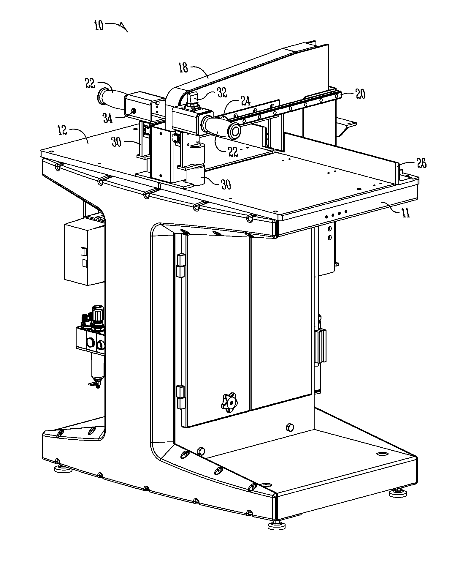
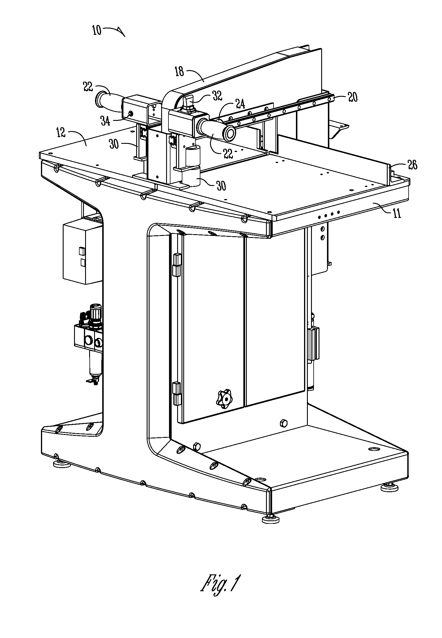
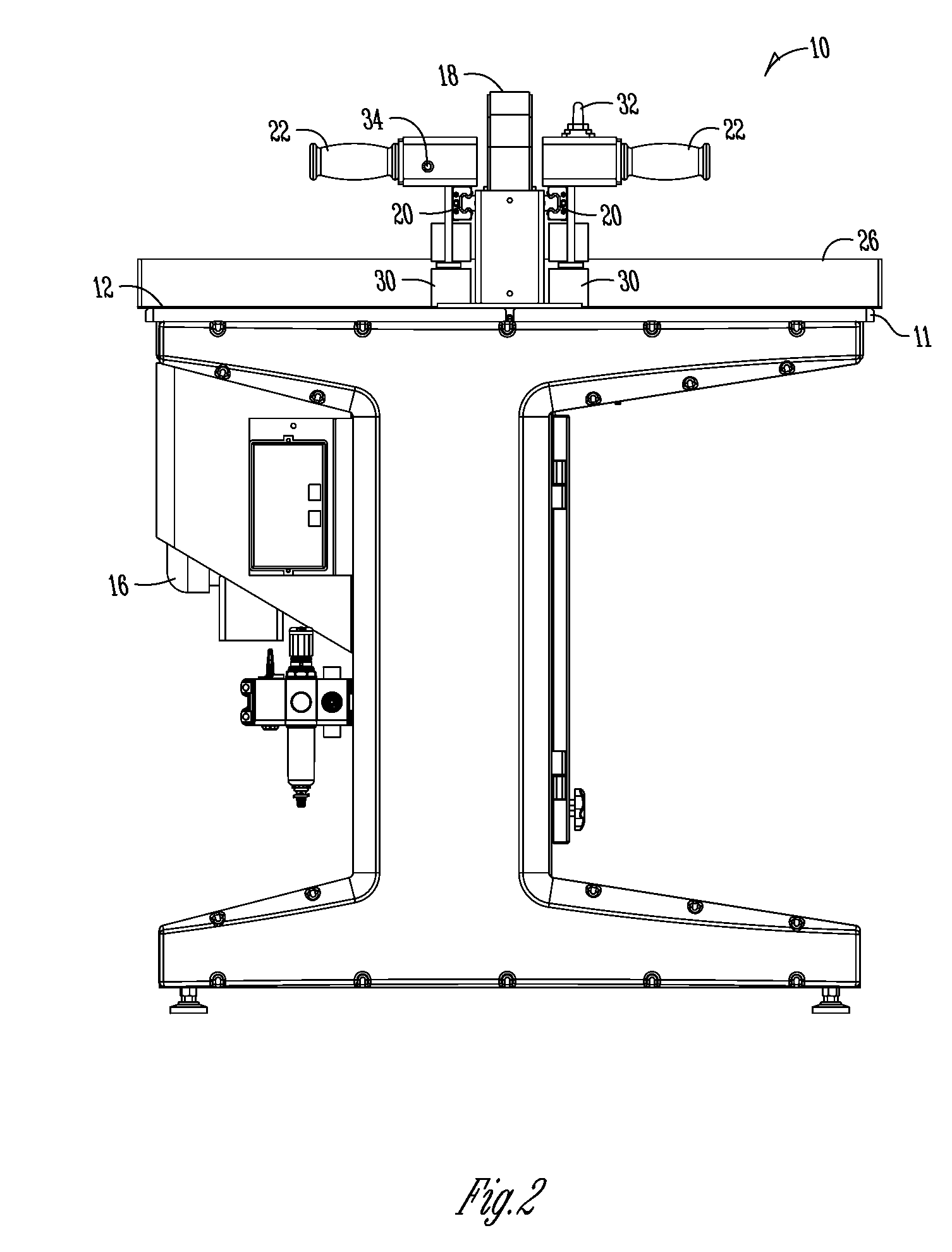
[0017]An improved safety device for an electrically powered crosscut saw is described and best shown in FIG. 1. An electrically powered crosscut saw 10 features a base 11 supporting a tabletop 12 through which a saw blade 14 (see FIG. 4) may pass in order to cut stock. The stock is secured by an operator against a back fence 26 so as to ensure a clean cut. A blade guard 18 is typically located on the tabletop 12 and aligned with the saw blade 14 such that when the saw blade 14 is cutting the stock, the operator is separated from the saw blade 14 by the blade guard 18. The blade guard 18 thereby protects the operator from debris during the cutting process, while also reducing the potential for contact between the operator and the saw blade 14. The blade guard 18 also acts as a top clamp and may move vertically to secure stock.

[0018]According to the preferred embodiment...


PUM

PropertyMeasurementUnit
timeaaaaaaaaaa
lengthaaaaaaaaaa
distanceaaaaaaaaaa

Abstract

An enhancement for use with automatically cycled saw systems that provides an operator access to two-hand anti-tie down buttons and other machine control functions while manually crowding the material to be cut against the saw's fence. The enhancement includes anti-tie down buttons to prevent a cutting cycle unless both buttons are depressed within preset time limit of each other.

Description

CROSS REFERENCE TO RELATED APPLICATIONS[0001]This application claims priority under 35 U.S.C. §119 to provisional application U.S. Ser. No. 61 / 021,189 filed Jan. 15, 2008, herein incorporated by reference in its entirety.INCORPORATED BY REFERENCE[0002]Please incorporate by reference the following in their entirety: U.S. Pat. No. 7,171,738 to Dick et al. issued Feb. 6, 2007; U.S. Pat. No. 4,736,511 to Jenkner issued April 1988; U.S. Pat. No. 4,830,075 to Jenkner issued May 1989; U.S. Pat. No. 6,640,855 to Giles issued November 2003; U.S. Application Publication No. 2003 / 0041919 to Giles published March 2003; and U.S. Pat. No. 7,031,789 to Dick et al. issued Apr. 1, 2006.FIELD OF THE INVENTION[0003]The present invention relates in general to methods and apparatus for sawing lineal material to length.BACKGROUND OF THE INVENTION[0004]Electrically powered crosscut saws have been in existence for decades and have been manufactured in many different configurations. In order to improve the ...

Claims


Application Information

Patent Timeline
Patent Type & Authority Patents(United States)
IPC IPC(8): F16P3/20B26D7/02
CPCB23D45/06B23D47/02B23D47/04B23D59/008Y10T83/7693Y10T83/445Y10T83/04Y10T83/773Y10T83/7567Y10T83/7734
Inventor HOSHOR, STEVEN T.
Owner TECHNOLOGY SERVICE CORPORATION
Why Eureka
Try Eureka