
Two-motor drive arrangement for a roller curtain

a technology of drive arrangement and roller curtain, which is applied in the direction of curtain suspension device, door/window protective device, wing accessories, etc., can solve the problems that the load on the motor can still cover a substantial range, and the counterbalance system employing several sets of concentrically arranged coil springs is necessary, so as to reduce the voltage requirements and reduce the torsional stress on the drive components.

Active Publication Date: 2013-06-04
MCKEON ROLLING STEEL DOOR
View PDF19 Cites 7 Cited by
  • Summary
  • Abstract
  • Description
  • Claims
  • Application Information

AI Technical Summary

Benefits of technology

The invention provides an electric motor at each end of the drum, which allows for smaller motors to be used and reduces torsional stresses on the drive components. This also reduces the voltage requirements, which means that upgraded wiring may not be necessary. Additionally, if one of the motors fails, the door may still be opened using the other motor and a manual assist.

Problems solved by technology

For doors that are particularly large and heavy, counterbalance systems employing several sets of concentrically arranged coil springs are necessary.
Notwithstanding the use of a counterbalance spring system, the load on the motor can still cover a substantial range, particularly for a large door.

Method used


Image

  • Two-motor drive arrangement for a roller curtain
  • Two-motor drive arrangement for a roller curtain
  • Two-motor drive arrangement for a roller curtain

Examples


Embodiment Construction

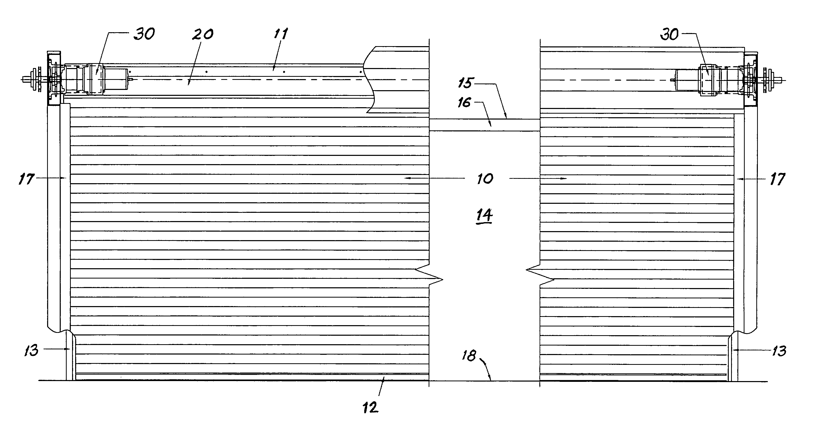
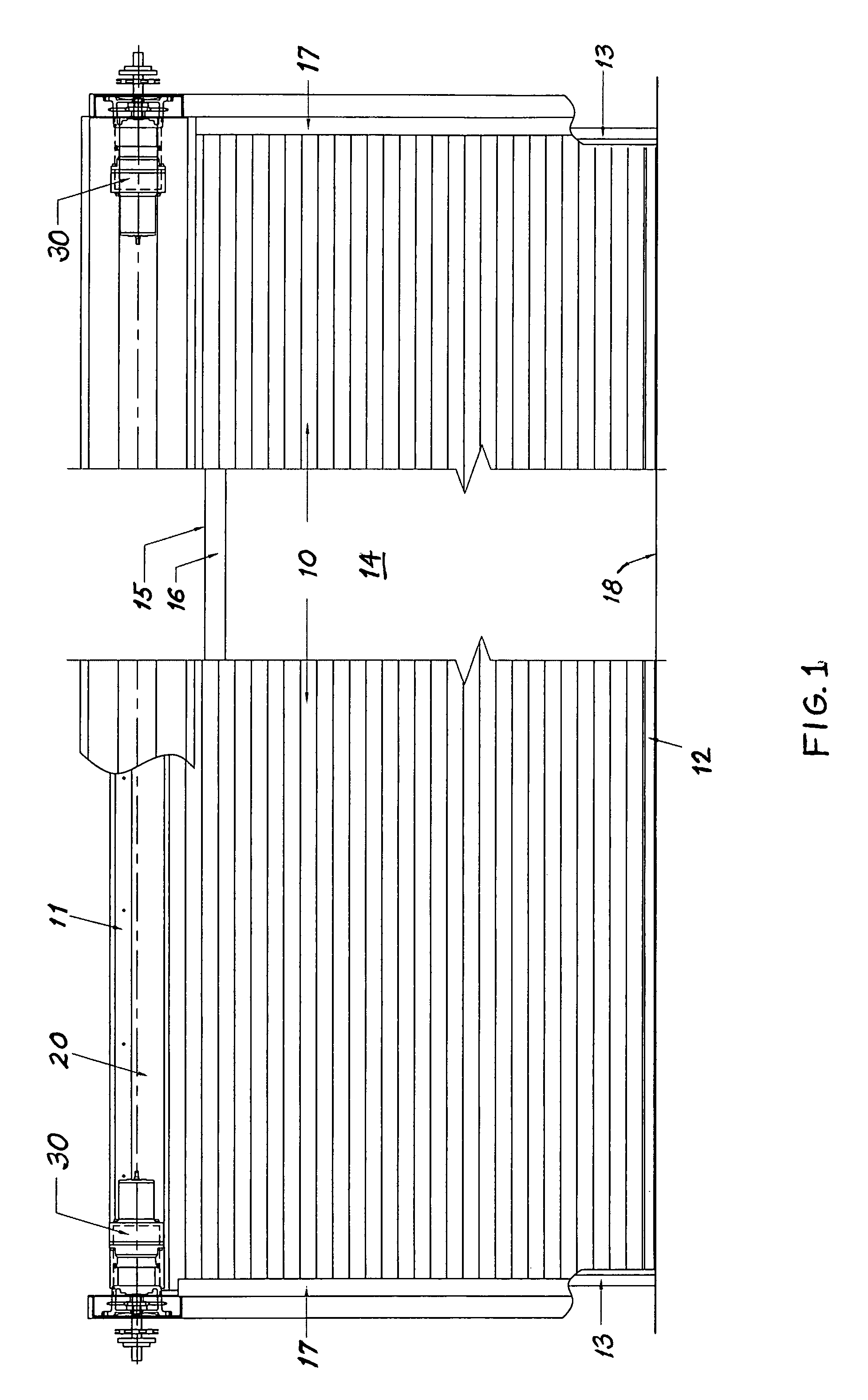
[0015]FIG. 1 shows a roller curtain 10 having a proximal edge 11 fixed to a drum 20, an opposing free edge 12, and lateral edges 13. In the closed position, as shown, the curtain 10 is unwound from drum 20 and extends to cover a vertical opening 14 defined by a frame 15 and floor 18. The frame 15 has a top 16 and side channels 17 which receive lateral edges 13 of the curtain. Motors 30 provided on opposite sides of the opening 14 provide the torque necessary to rotate the drum 20 and coil the curtain 10 thereon, as will be described.

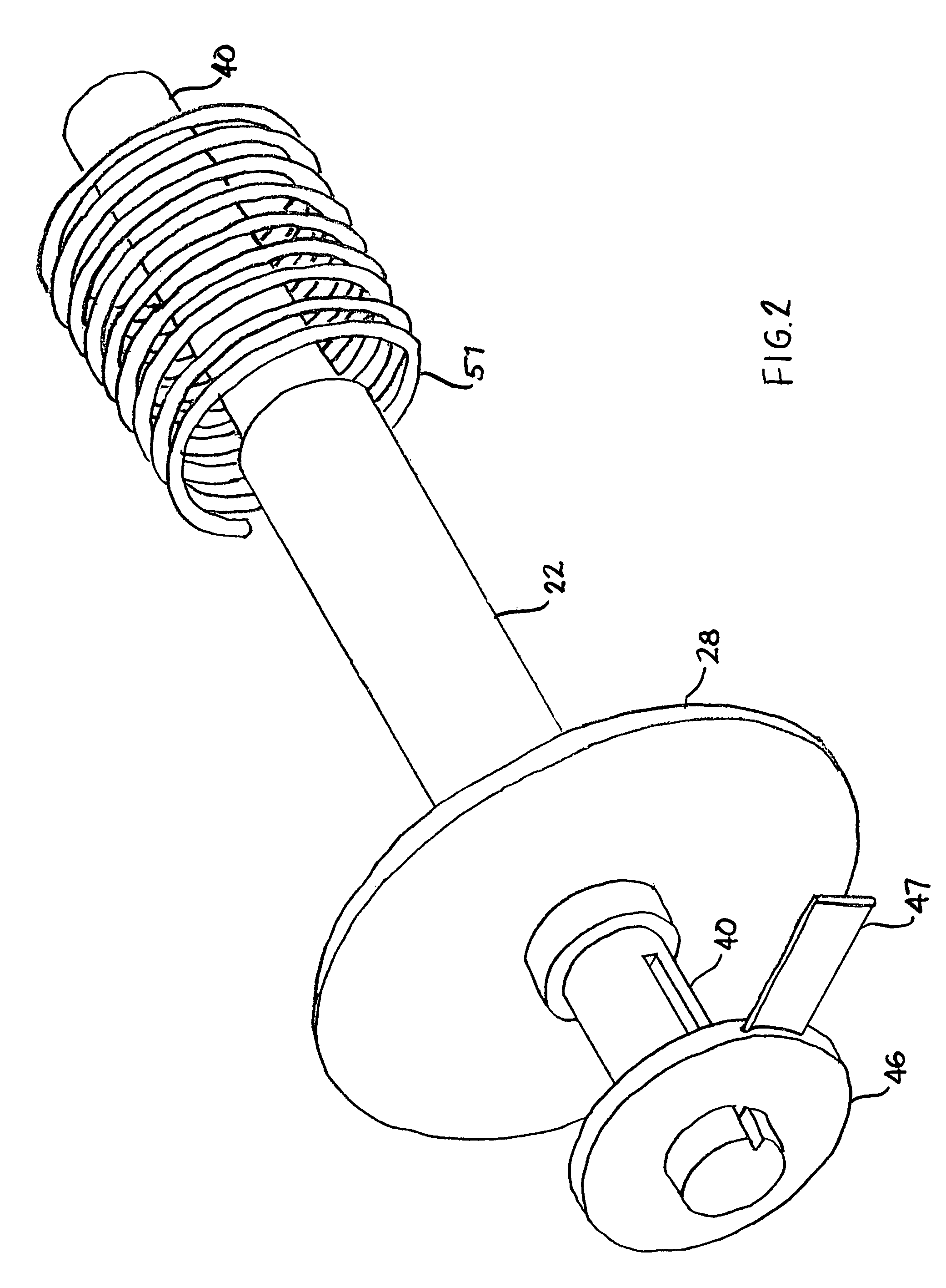
[0016]FIG. 2 shows the basic drive components for one side of the drive arrangement. These components include a hollow drive shaft 22 to which a driven sprocket 28 is fixed; a tension shaft 40 that is received through the hollow drive shaft 22 and is fixed to the door frame by a tension wheel 46 having a lever 47; and a torsion spring 51 that provides torsional loading between the hollow drive shaft 22 and the tension shaft 40. At the time of installatio...


PUM


Abstract

A drive arrangement for a roller curtain covering an opening defined by a frame includes a drum mounted horizontally across one side of the opening, a pair of hollow drive shafts fixed against rotation in opposite ends of the drum, and a pair of coaxial tension shaft portions fixed to the frame and received through respective hollow drive shafts. At least one coil spring is associated with each tension shaft portion, each spring having a first end fixed to a tension shaft portion and a second end fixed to the drum. A pair of drive motors are operatively connected to respective hollow drive shafts for synchronously rotating the drive shafts in order to coil a roller curtain on the drum.

Description

BACKGROUND OF THE INVENTION[0001]1. Field of the Invention[0002]The invention relates a drive arrangement for a spring-loaded roller curtain, which is wound on a horizontally mounted drum.[0003]2. Description of the Related Art[0004]Roller curtains for covering large openings such as hallways and open walls in buildings are well known. As used herein the term “roller curtain” will be understood to mean a plurality of slats that are hinged together so that the curtain can be wound on a drum. Such slats may be either insulated or uninsulated, and the gauge of the metal may vary depending on the application, e.g. as acoustical barriers or fire doors. Hinging and mounting arrangements are well known and will not be discussed herein.[0005]A roller curtain is typically wound on a drum by driving the drum in rotation using an electric motor. Counter-balance systems employing torsionally loaded coil springs are well known for reducing the torque necessary to rotate the drum, especially for ...

Claims


Application Information

Patent Timeline
Patent Type & Authority Patents(United States)
IPC IPC(8): E06B9/56E05F15/00A47H1/00E05F11/00E05F13/00A47G5/02
CPCE06B9/70E06B9/60
Inventor LAMBRIDIS, ANDREW C.GOMAA, ASHRAF
Owner MCKEON ROLLING STEEL DOOR
Learn More