
Capacitive micro-machined ultrasonic transducer for element transducer apertures

a micro-machined ultrasonic transducer and element technology, applied in the field of ultrasonic transducers, can solve the problems of compromising performance and/or cost, affecting the intrinsic acoustic behavior of the transducer device, and difficult effect of geometric parameters set at this initial stage, so as to enhance the electrical impedance characteristics of the transducer

Active Publication Date: 2013-06-04
VERMON
View PDF12 Cites 16 Cited by
  • Summary
  • Abstract
  • Description
  • Claims
  • Application Information

AI Technical Summary

Benefits of technology

[0017]With the above described prior art as a background, and also considering the relevant background with respect to synthetic beamforming techniques for slotted transducers, in accordance with one aspect of the invention, ultrasonic devices (whether single elements or arrays) that are used for imaging and that employ capacitive micromachined membranes are greatly improved through the implementation of novel methods of mapping transducer surfaces so as to customize the acoustic radiation of the transducer apertures according to the requirements of high quality or harmonic imaging systems and so as to enhance the electrical impedance characteristics of the transducer devices with respect to the associated electronics.
[0018]Another aspect of the present invention concerns the provision of a method of shaping a CMUT device which includes customized optimization or apodization (weighting) of the CMMs forming the transducer surface. Preferably, the apodization of the CMMs is performed in amplitude and / or in frequency to enhance the quality of the acoustic beam pattern and, in particular, so as to decrease the side lobes (for arrays) or the lateral lobes (for single surfaces) of the devices.
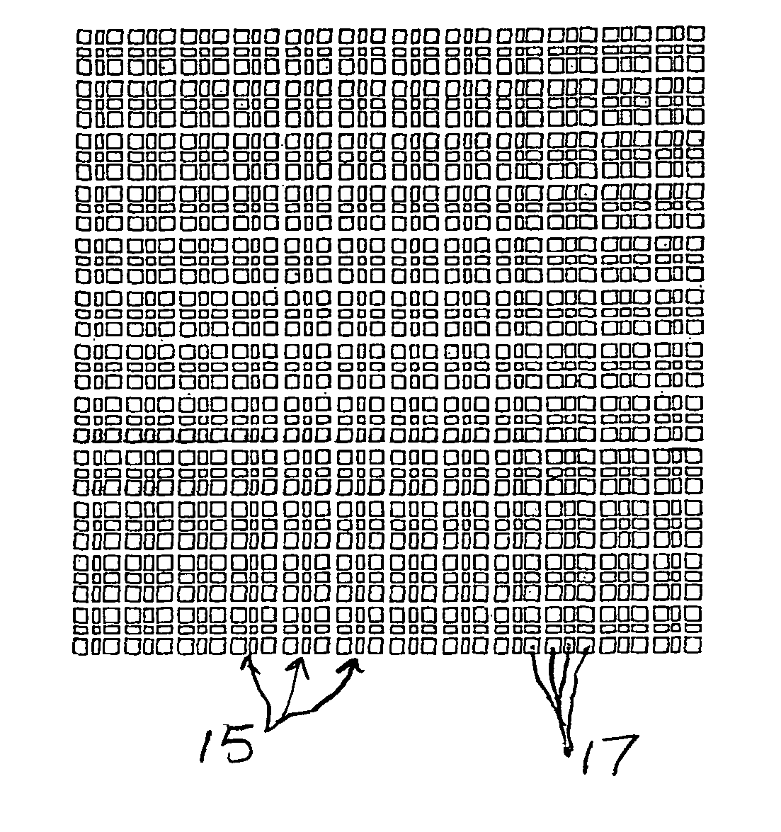
[0022]In accordance with another aspect thereof, the present invention relates to particular surface mapping configurations of a Capacitive Micromachined Ultrasonic Transducer (CMUT) where Capacitive Micromachined Membranes (CMM) are specifically tailored and arranged on the front surface of the transducer device so as to enable customization of the acoustical and electrical behavior of the device. The method of this aspect of the invention is well suited to arrayed imaging transducers wherein the characteristics of the individual transducers are crucial in achieving quality images. However, the method is also applicable to single surface (area) transducing devices, and when so implemented, this method prevents edge effects and significantly improves the acoustical beam pattern and / or frequency response, thereby enabling a designer to custom shape of the acoustical output of the transducer device whatever the footprint of device.
[0023]In another aspect of the invention, the arrangement of the CMMs over the surface CMUT provides the surface with an optimized apodization function, thus improving the output acoustical beam pattern. The apodization functions that can be employed include those based on well known gaussian or hamming distribution functions commonly used in advanced imaging. Advantageously, the apodization obtained with specific sampling of the CMMs can be used to simultaneously control both the amplitude and resonant frequency of the transducer device without any compromising of the intrinsic performance of the device.
[0024]Yet another aspect of the invention concerns apodization of the elemental apertures of array transducers. Generally speaking, an array transducer designed for use in imaging applications is comprised of a plurality of independently individually addressable elements or element apertures. In accordance with this aspect of the present invention, the addressable elements are individually formed by a plurality of CMMs having a shape and an area which are optimized to provide an amplitude and frequency apodization function in both the azimuth and elevation directions. Application of this method to transducer array devices provides a customized smoothing of the physical boundaries of the transducer elements, thereby preventing the occurrence of side lobes.
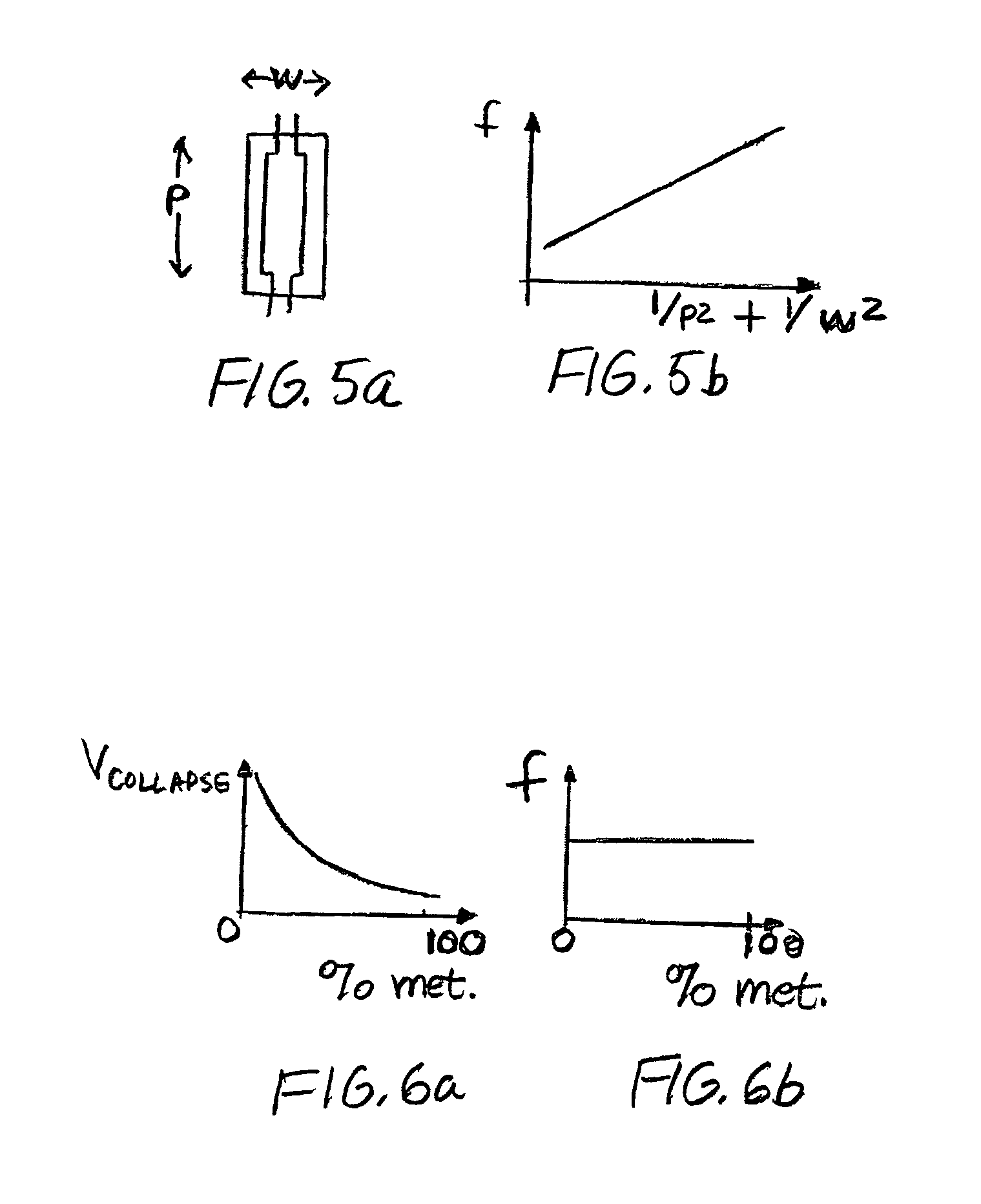
[0025]A further aspect of the invention is concerned with an improvement of the electrical behavior of the CMUT devices, particularly in arrayed transducer constructions wherein the transducer elements are of very narrow dimensions and the electrical impedance thereof is inherently highly mismatched to that of the transmission line, thereby creating spurious reflections and signal disturbances that affect the pulse shape and frequency response accordingly. The physical characteristics of the CMMs are tailored so as to maximize the capacitance of the membranes, thereby enhancing the efficiency of the elements of the transducer array. The value of the electrical impedance (specifically, the imaginary part) of the array elements is, therefore, reduced, and thus the elements are seen as more resistive than in conventional CMUT designs.

Problems solved by technology

Further modification of the geometric parameters set at this initial stage is difficult to effect, and, further, will strongly affect the intrinsic acoustic behavior of the transducer device.
Usually, taking advantage of any trade-offs with respect to the geometrical specifications of a transducer involves compromise regarding performance and / or cost.
Conversely, when a pressure force acts on the surfaces of the biased membranes, this results in mechanical bending of the membranes and, thus, in creation of an output voltage oscillation.
Although inherent drawbacks in such capacitive devices still remain (e.g., drawbacks such as device fragility, a biased voltage requirement, a long prototyping cycle, and high volume production needs) such drawbacks will likely be overcome with advances in the microelectronics and sensors technologies.
Although methods such as those based on coded signals or post-calculated signals can be of suitable efficiency, the implementation of such methods in commercial systems presents another challenge.
Unfortunately, when this approach is applied to circular shaped CMUT cells as disclosed by Savord et al.
Earlier CMUT devices that have been shaped to form arrays were not diced, and measurements carried out with respect to such devices have demonstrated that the bulky silicon kerfs employed provide a very weak acoustic barrier so that the image quality provided by such devices is quite inferior to that of standard transducer devices.
This process is limited by the great fragility of the substrate after the grinding operation, thus making all further manufacturing operations more delicate than with conventional techniques.

Method used


Image

  • Capacitive micro-machined ultrasonic transducer for element transducer apertures
  • Capacitive micro-machined ultrasonic transducer for element transducer apertures
  • Capacitive micro-machined ultrasonic transducer for element transducer apertures

Examples


Embodiment Construction

[0047]Before describing the preferred embodiments of the invention, it is noted that in the discussion below, the term “element transducer” (or “element transducers”) refers to a sub-element aperture of an array transducer and usually comprises a plurality of transducer elements arranged on the full aperture. The term is only applicable to array type transducer apparatus and is not used in connection with single surface transducers. The term “CMM” (or “CMMs”) designates capacitive cells that are machined on or etched into the surface of a silicon substrate in such a manner as to form a transducer surface when a sufficient number of cells are provided. The term “CMUT” (or “CMUTs”) designates an ultrasonic transducer comprising a plurality of CMMs or a plurality of CMM groups.

[0048]As indicated above in the description of the prior art, CMUT devices can be shaped in various ultrasonic transducer configurations whatever the application or modality. In the following detailed description...


PUM

PropertyMeasurementUnit
thicknessaaaaaaaaaa
electrical impedanceaaaaaaaaaa
dimensionsaaaaaaaaaa

Abstract

A capacitive micro-machined ultrasonic transducer (CMUT) array includes an improved elementary aperture for imaging operations. The transducer can be of a linear, curved linear, annular, matrix or even single surface configuration. The elementary apertures thereof are formed by a specific arrangement of capacitive micromachined membranes (CMM) so as to exhibit ideal acoustical and electrical behavior when operated with imaging systems. The CMM arrangements can be either conventional where the element transducers of the array are uniformly shaped by predefined CMMs in a manner such as to exhibit acoustic behavior similar to a piezoelectric transducer, or can be more sophisticated, wherein each element transducer is formed by a specific combination of different CMMs (i.e., of a different size and / or shape) so as to provide the transducer with built-in acoustic apodization that can be implemented in the azimuth and / or elevation dimension of the device.

Description

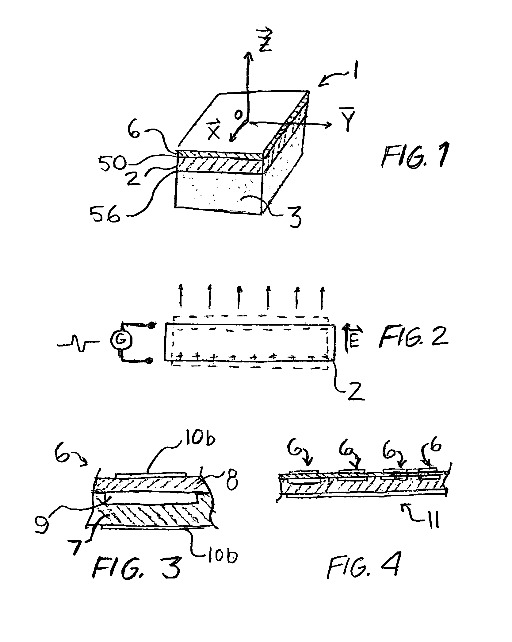
FIELD OF THE INVENTION[0001]The present invention relates to ultrasonic transducers and, more particularly, to capacitive micro-machined ultrasonic transducers.BACKGROUND OF THE INVENTION[0002]Ultrasonic transducers are typically formed with one vibrating surface or a plurality of vibrating surfaces capable of converting electrical energy into mechanical displacements and vice-versa. Because the acoustic pressure produced by such devices obeys diffracting laws, physical parameters such as area, frequency, bandwidth, geometry and surface apodization (weighting) are key factors in transducer design and actually govern the radiating acoustic beam pattern produced by the transducer.[0003]The operation of single area transducers is often characterized by spurious boundary effects, which are manifested by secondary lobes occurring laterally of the main lobe. These effects generally occur when the ratio factor between the Z and the X-Y dimensions does not satisfy a certain value. On the ot...

Claims


Application Information

Patent Timeline
Patent Type & Authority Patents(United States)
IPC IPC(8): H04R19/00
CPCB06B1/0292H04R19/00Y10T29/42
Inventor FELIX, NICOLASFLESCH, AIMEDUFAIT, REMINGUYEN-DINH, AN
Owner VERMON
Learn More