Method and system for enhancing optical efficiency for an EAMR head

a technology of optical efficiency and eamr head, which is applied in the field of method and system for enhancing optical efficiency of eamr head, can solve the problems of low efficiency

Active Publication Date: 2013-06-04
WESTERN DIGITAL TECH INC
View PDF19 Cites 155 Cited by
  • Summary
  • Abstract
  • Description
  • Claims
  • Application Information

AI Technical Summary

Benefits of technology

[0004]A method and system for providing an EAMR transducer and a waveguide used therein are described. The EAMR transducer is coupled with a laser that provides energy to the EAMR transducer. The EAMR transducer has an ABS configured to reside in proximity to a media during use. The EAMR transducer includes a write pole configured to write to a region of the media, at least one coil for energizing the write pole, and a near field transducer (NFT) proximate to the ABS. The NFT is for focusing the energy onto the regi

Problems solved by technology

Although the conventional EAMR transducer 10 may function, it may b

Method used


Image

  • Method and system for enhancing optical efficiency for an EAMR head
  • Method and system for enhancing optical efficiency for an EAMR head
  • Method and system for enhancing optical efficiency for an EAMR head

Examples


Embodiment Construction

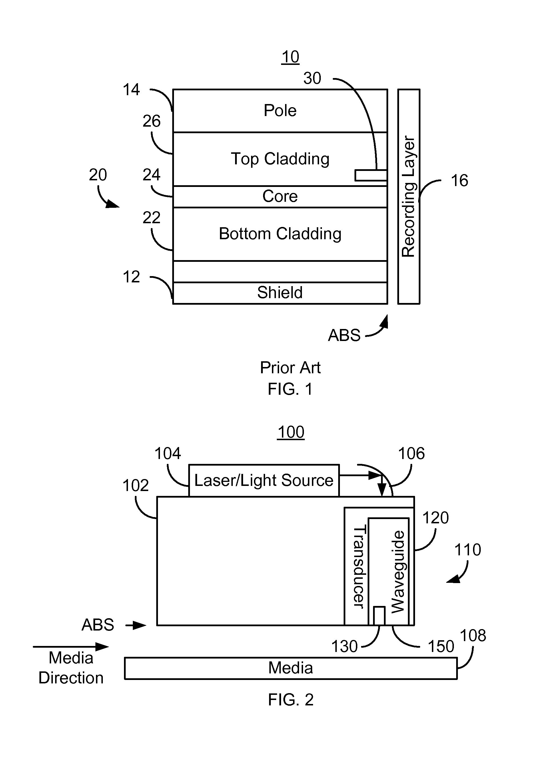
[0013]FIG. 2 is a diagram depicting a portion of an EAMR disk drive 100. For clarity, FIG. 2 is not to scale. For simplicity not all portions of the EAMR disk drive 100 are shown. In addition, although the disk drive 100 is depicted in the context of particular components other and / or different components may be used. Further, the arrangement of components may vary in different embodiments. The EAMR disk drive 100 includes a slider 102, a laser / light source 104, optional mirror or other optics 106 for redirecting light from the laser 104, media 108, and an EAMR head 110. In some embodiments, the laser 104 is a laser diode. Although shown as mounted on the slider 102, the laser 104 may be coupled with the slider 102 in another fashion. For example, the laser 104 might be mounted on a suspension (not shown in FIG. 2) to which the slider 102 is also attached. The laser 104 may also be oriented differently and / or optically coupled with the EAMR transducer 120 in another manner. The medi...


PUM


Abstract

A method and system for providing an EAMR transducer and a waveguide used therein are described. The EAMR transducer is coupled with a laser that provides energy. The EAMR transducer also has an ABS that resides in proximity to a media during use. The EAMR transducer includes a waveguide, a write pole to write to a region of the media, coil(s) for energizing the write pole, and a near field transducer (NFT) proximate to the ABS for focusing the energy onto the media. The waveguide includes a mode shift compensator, first and second cladding layers, and a core between the cladding layers. The core directs energy from the laser toward the ABS and has a core index of refraction. The core is also between the mode shift compensator and the NFT. The mode shift compensator has a mode shift compensator index of refraction less than the core index of refraction.

Description

BACKGROUND[0001]FIG. 1 depicts a portion of a conventional energy assisted magnetic recording (EAMR) transducer 10 as well as recording media 16. For clarity, FIG. 1 is not to scale. The conventional EAMR transducer 10 is used in writing to the recording media 16. The EAMR transducer 10 receives light, or energy, from a conventional laser (not shown in FIG. 1). The conventional EAMR transducer 10 includes a conventional waveguide 20, which directs the light toward the media 16. The conventional waveguide typically includes a core 24 and cladding 22 and 26. Also shown are a conventional shield 12, a conventional pole 14, and a conventional near-field transducer (NFT) 30. Light from a laser (not shown) is incident on the grating (not shown), which couples light to the waveguide 20. Light is guided by the conventional waveguide 20 to the NFT 30 near the air-bearing surface (ABS). The light interacts with the NFT 30, which absorbs part of the optical energy and forms very strong localiz...

Claims


Application Information

Patent Timeline
IPC IPC(8): G11B11/00
CPCG11B5/314G11B5/6088G11B2005/0021
Inventor SHI, ZHONGLEE, SHINGYUAN, HONGXINGIKKAWI, RABEE M.
Owner WESTERN DIGITAL TECH INC
Why Eureka
Try Eureka