Guiding system for a metal strip at a rolling mill outlet

a technology of guiding system and metal strip, which is applied in metal rolling, metal rolling arrangements, transportation and packaging, etc., can solve the problems of increasing the possibility of head folding and cobbles, and parts cannot meet the necessary quality requirements, so as to improve the winding quality of the coil itsel

Active Publication Date: 2013-06-11
DANIELI & C OFF MEC SPA
View PDF30 Cites 1 Cited by
  • Summary
  • Abstract
  • Description
  • Claims
  • Application Information

AI Technical Summary

Benefits of technology

[0017]It is the primary object of the present invention to make a roller guiding system for thin strips at a rolling plant outlet which allows to act on the mechanical-aerodynamic phenomenon which causes instability in the moving strip head, said guiding system being self-centering and therefore suitable for improving the winding quality of the coil itself.
[0018]Another object of the invention is to avoid that the strip, moving downwards, can impact onto the feeding rollers of the roller table underneath, getting damaged or cobbled and causing the interruption of the feeding of the strip itself towards the winding assembly.
[0019]A further object of the invention is to prevent the strip, moving upwards, from impacting or sliding on the upper containment devices avoiding possible damages to the surface, such as scratches or lines.

Problems solved by technology

Disadvantageously, the high speed of the head of the strip and the thin thickness of the strip itself increase the possibility of head folding and cobbles.
A first disadvantage is the generation of a permanent deformation in a part of the strip in proximity of the head implying a rejection of said part of the strip for each wound coil, because this part cannot meet the necessary quality requirements.
A second disadvantage is represented by the fact that the shape of the strip head thus obtained may cause cobbles when it encounters the pinch / deflector roller or the lead-in tables of the winding assembly.

Method used


Image

  • Guiding system for a metal strip at a rolling mill outlet
  • Guiding system for a metal strip at a rolling mill outlet
  • Guiding system for a metal strip at a rolling mill outlet

Examples


Embodiment Construction

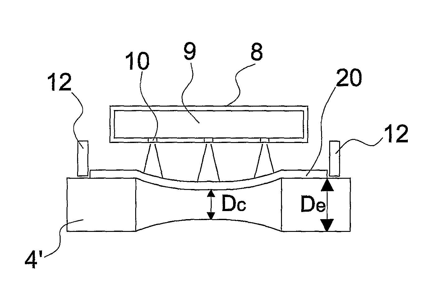
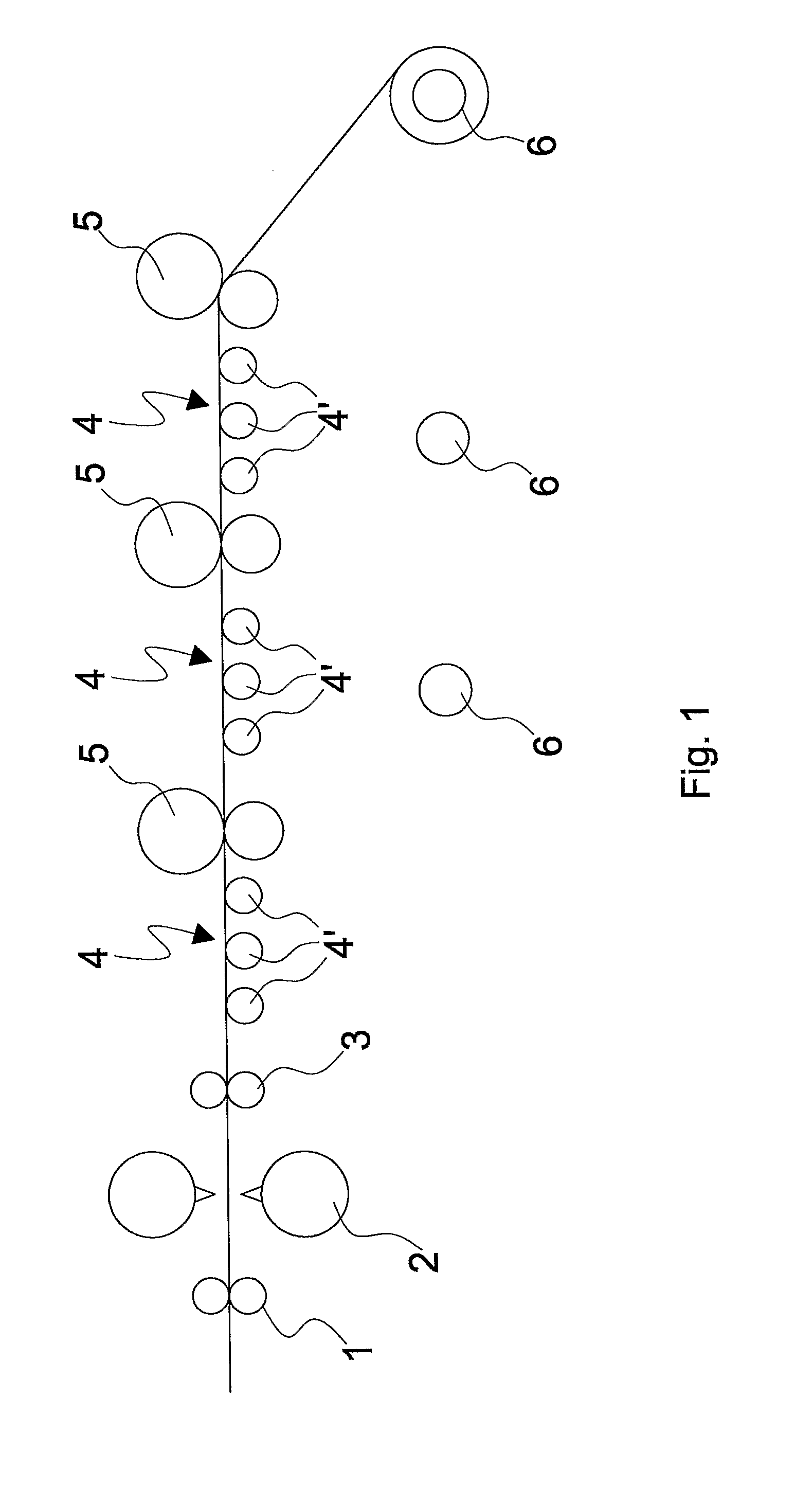
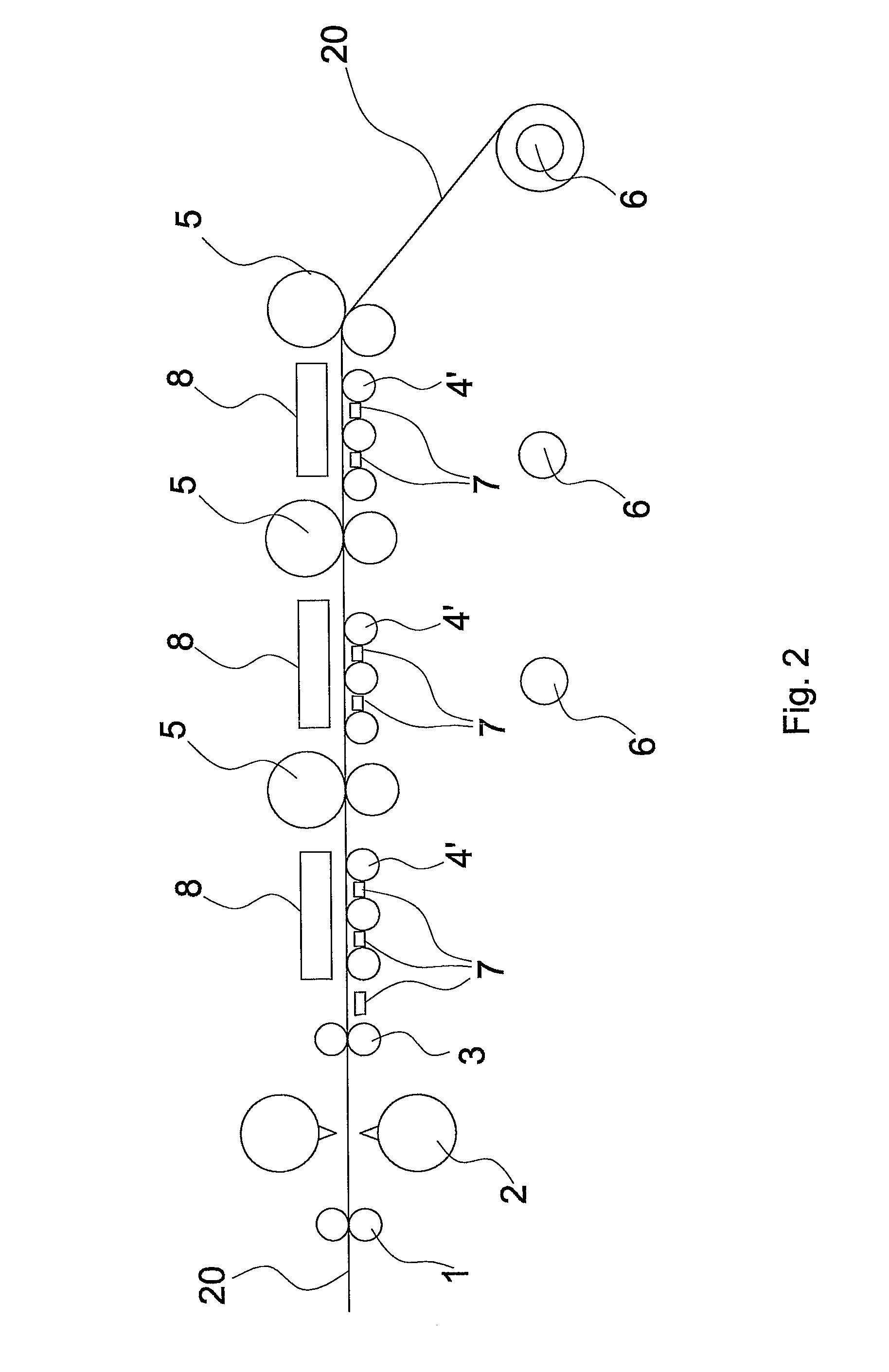
[0047]FIG. 1 shows a roller guiding system for thin or ultra-thin metal strips 20 exiting from a hot rolling mill, either endless or of the traditional type, comprising:[0048]a flying shear 2 for cutting the strip;[0049]a pair of pinch rolls 1, arranged at the finishing mill outlet, and upstream of the shear 2, suitable for drawing the head of the strip after the cut;[0050]a pair of pinch and stiffening rollers 3 of the strip;[0051]at least one motorized roller table 4, comprising a plurality of feeding rollers 4′ of the strip towards at least one winding section of the strip;[0052]a possible pair of pinch and deflector rollers 5 at the end of said at least one roller table 4;[0053]at least one winder 6, provided with at least one winding roller, at each pair of pinch / deflector rollers 5.

[0054]FIG. 3 diagrammatically shows the strip moving along a roller guiding system of the known art and shows the effect of instability due to the collision (FIG. 3(b)) of the head of the strip on a...


PUM

PropertyMeasurementUnit
angleaaaaaaaaaa
angleaaaaaaaaaa
thicknessaaaaaaaaaa

Abstract

A roller guiding system for thin strips (20) at a rolling system outlet which allows a safe guiding without take-off and consequent tipping / folding of the head of the strip and without cobbles even at high feeding speeds. The system of the invention prevents the strip from impacting or sliding on the upper containment devices (8) or on the rollers (4′) by its upwards or downwards movement, thus avoiding possible damages to the surface, such as scratches or lines. Furthermore, such a guiding system acts on the mechanical-aerodynamic phenomenon which causes instability in the head moving by making a self-centering guiding system which is thus suitable for improving the winding quality of the coil itself.

Description

FIELD OF THE INVENTION[0001]The present invention relates to a roller guiding system for metal strips, specifically to a guiding system for thin metal strips exiting from a rolling plant.STATE OF THE ART[0002]In the hot rolling of ultra-thin metal strips, i.e. strips having a thickness lower than 1.5 mm, the best technique for reaching the predetermined thickness is that of endless rolling in which the deformation process of the strip occurs without interruption.[0003]By applying such a rolling system for producing coils of strips, a flying shear which cut the strip when the wound coil reaches the expected dimensions is needed.[0004]The cut is performed at the speed of the strip at the finishing mill outlet, at a speed generally either equal to or higher than 12 m / s. Disadvantageously, the high speed of the head of the strip and the thin thickness of the strip itself increase the possibility of head folding and cobbles.[0005]The phenomenon which limits the maximum feeding speed of t...

Claims


Application Information

Patent Timeline
Patent Type & Authority Patents(United States)
IPC IPC(8): B21B39/20
CPCB21B39/008B21B39/12B21C47/34B21C47/3475B65G13/00B65G39/02B65G47/66B21B39/02
Inventor POLONI, ALFREDOVIGNOLO, LUCIANOSANDRIN, LUCAVECCHIET, FABIONOBILE, MATTEO
Owner DANIELI & C OFF MEC SPA
Why Eureka
Try Eureka