Multi-axis capacitive accelerometer

a capacitive accelerometer and multi-axis technology, applied in the field of accelerometers, can solve the problems of affecting the performance of cross-axis sensitivity, requiring the size and cost of a multi-axis accelerometer, and poor cross-axis sensitivities, so as to reduce the structure dimension reduce interference, and increase the linearity of the multi-axis capacitive accelerometer

Active Publication Date: 2013-06-11
IND TECH RES INST
View PDF44 Cites 13 Cited by
  • Summary
  • Abstract
  • Description
  • Claims
  • Application Information

AI Technical Summary

Benefits of technology

[0008]Accordingly, the disclosure is directed to a multi-axis capacitive accelerometer with a smaller size and excellent performances including high sensitivity, high linearity and low cross-axis sensitivity.
[0011]In the disclosure, since each of the different masses has an independent spring structure of their own, so that the disclosure can reduce the interference caused by the cross-axis sensitivity and effectively increase the linearity of the multi-axis capacitive accelerometer. In addition, since both the second mass and the third mass are disposed on the first mass, the disclosure can also effectively reduce the structure dimension of the multi-axis capacitive accelerometer.

Problems solved by technology

Especially for the applications in modern consumer electronic devices, the size and cost of a multi-axis accelerometer is demanded.
The design likes this will cause cross-axis sensitivities poor.
This may affect the performance of cross-axis sensitivity seriously.
In addition, the motion of the proof mass for sensing Z-axis acceleration disclosed by U.S. Pat. No. 6,845,670 may be a combination of rotation and movement, and this may results in poor linearity of the accelerometer.
U.S. Pat. No. 7,258,012 which disclosed another accelerometer design with one sensing structure, but the motion of its Z-axis proof mass also may lead the Z-axis output with poor linearity.

Method used


Image

  • Multi-axis capacitive accelerometer
  • Multi-axis capacitive accelerometer
  • Multi-axis capacitive accelerometer

Examples


Embodiment Construction

[0019]Reference will now be made in detail to the embodiments of the disclosure, examples of which are illustrated in the accompanying drawings. Wherever possible, the same reference numbers are used in the drawings and the description to refer to the same or like parts.

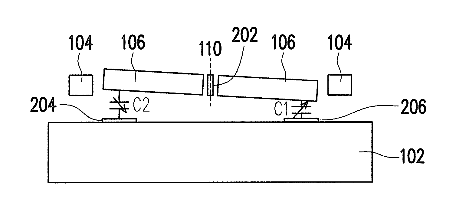
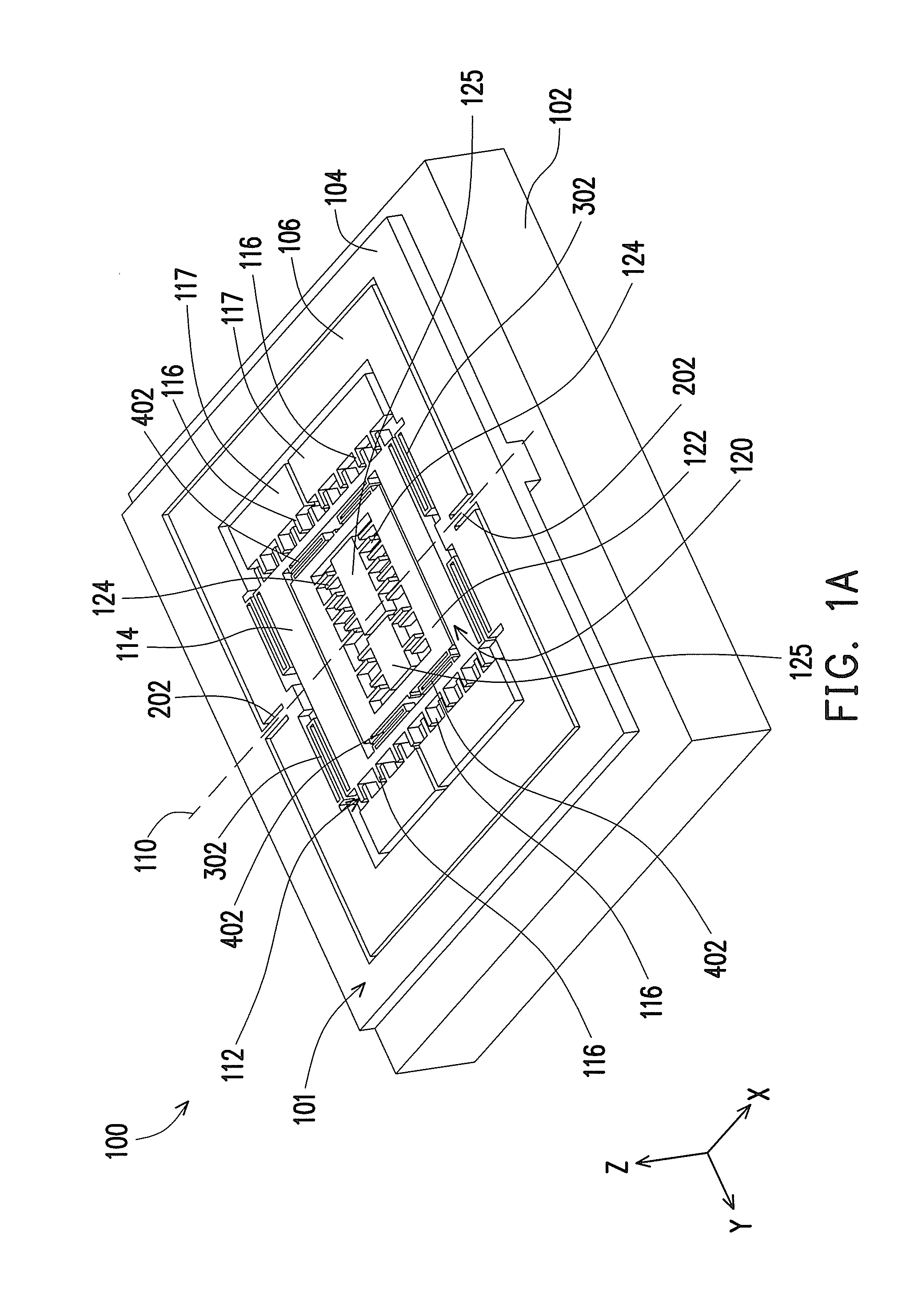
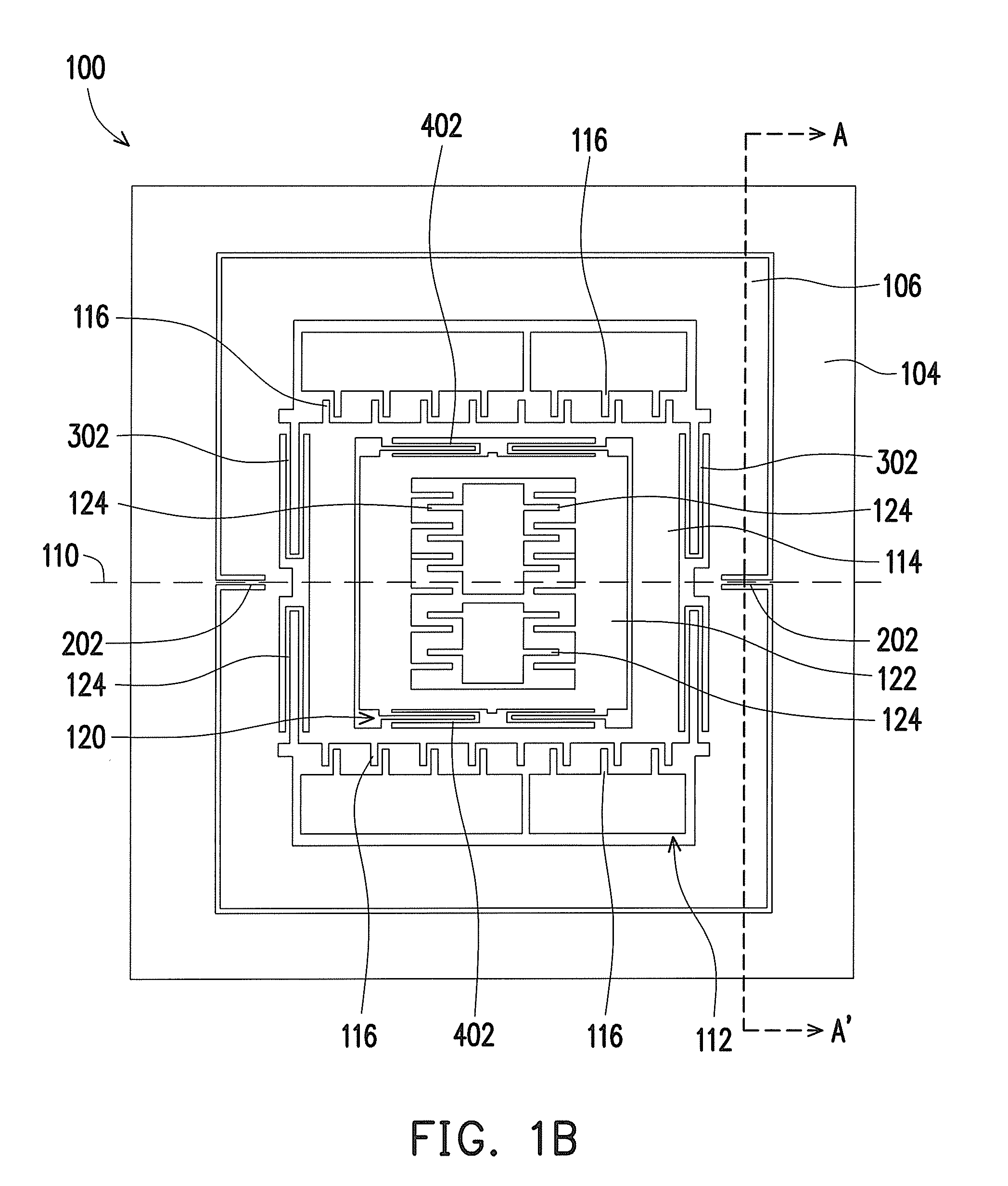
[0020]FIG. 1A is a 3-dimensions diagram of a multi-axis capacitive accelerometer according to an embodiment of the disclosure and FIG. 1B is a top-view diagram of the multi-axis capacitive accelerometer of FIG. 1A. Referring to FIGS. 1A and 1B, a multi-axis capacitive accelerometer 100 provided by the embodiment includes a substrate 102 and an element structure layer 101. The element structure layer 101 comprises an anchor 104, a first mass 106, a second mass 114, a first independent set of springs 202, a second independent set of springs 302 and at least a comb-shaped set of capacitors 116. The anchor 104 herein is fixed on the substrate 102, the first mass 106 is asymmetrically suspended on the anchor 104 by means ...


PUM


Abstract

A multi-axis capacitive accelerometer is disclosed. A first mass is disposed and held by an anchor supported by a substrate, wherein the first mass is asymmetrically suspended on the anchor by means of two cantilevers, so that the first mass rotates about a rotation axis, for sensing the acceleration in a first direction perpendicular to the substrate. A second mass is disposed in the first mass and suspended on the first mass by means of a set of springs to sense the acceleration in a second direction parallel to the substrate. Furthermore, a third mass can be disposed in the second mass, wherein the third mass is suspended on the second mass by means of another set of springs to sense the acceleration in a third direction. The first direction, the second direction and the third direction are mutually orthogonal to each other.

Description

CROSS-REFERENCE TO RELATED APPLICATION[0001]This application claims the priority benefit of U.S.A. provisional application Ser. No. 61 / 094,411, filed on Sep. 5, 2008, all disclosures are incorporated therewith. This application also claims the priority of Taiwan application serial no. 97134219, filed on Sep. 5, 2008. The entirety of each of the above-mentioned patent applications is hereby incorporated by reference herein and made a part of this specification.BACKGROUND[0002]1. Technical Field[0003]The disclosure relates to an accelerometer which is manufactured by Micro Electro Mechanical System (MEMS) technology and has the capability of sensing two axes or three axes acceleration.[0004]2. Description of Related Art[0005]Many non-military applications require accelerometer with the ability to sense acceleration along three mutually orthogonal axes. Especially for the applications in modern consumer electronic devices, the size and cost of a multi-axis accelerometer is demanded. Th...

Claims


Application Information

Patent Timeline
Patent Type & Authority Patents(United States)
IPC IPC(8): G01P15/125
CPCG01P15/125G01P15/18G01P2015/0814G01P2015/082G01P2015/0831
Inventor HSU, YU-WENCHIEN, HSIN-TANGCHEN, SHEAH
Owner IND TECH RES INST
Why Eureka
Try Eureka