Luggage with integrated vacuum bags

a vacuum bag and luggage technology, applied in the field of luggage, can solve the problems of not being able to increase the packing efficiency of the suitcase, the overall size of the suitcase is not designed to increase the packing efficiency, and the items contained within the suitcase cannot be repacked during use, so as to achieve the effect of increasing the packing efficiency of the suitcas

Inactive Publication Date: 2013-06-11
EFRON CHAD
View PDF17 Cites 36 Cited by
  • Summary
  • Abstract
  • Description
  • Claims
  • Application Information

AI Technical Summary

Benefits of technology

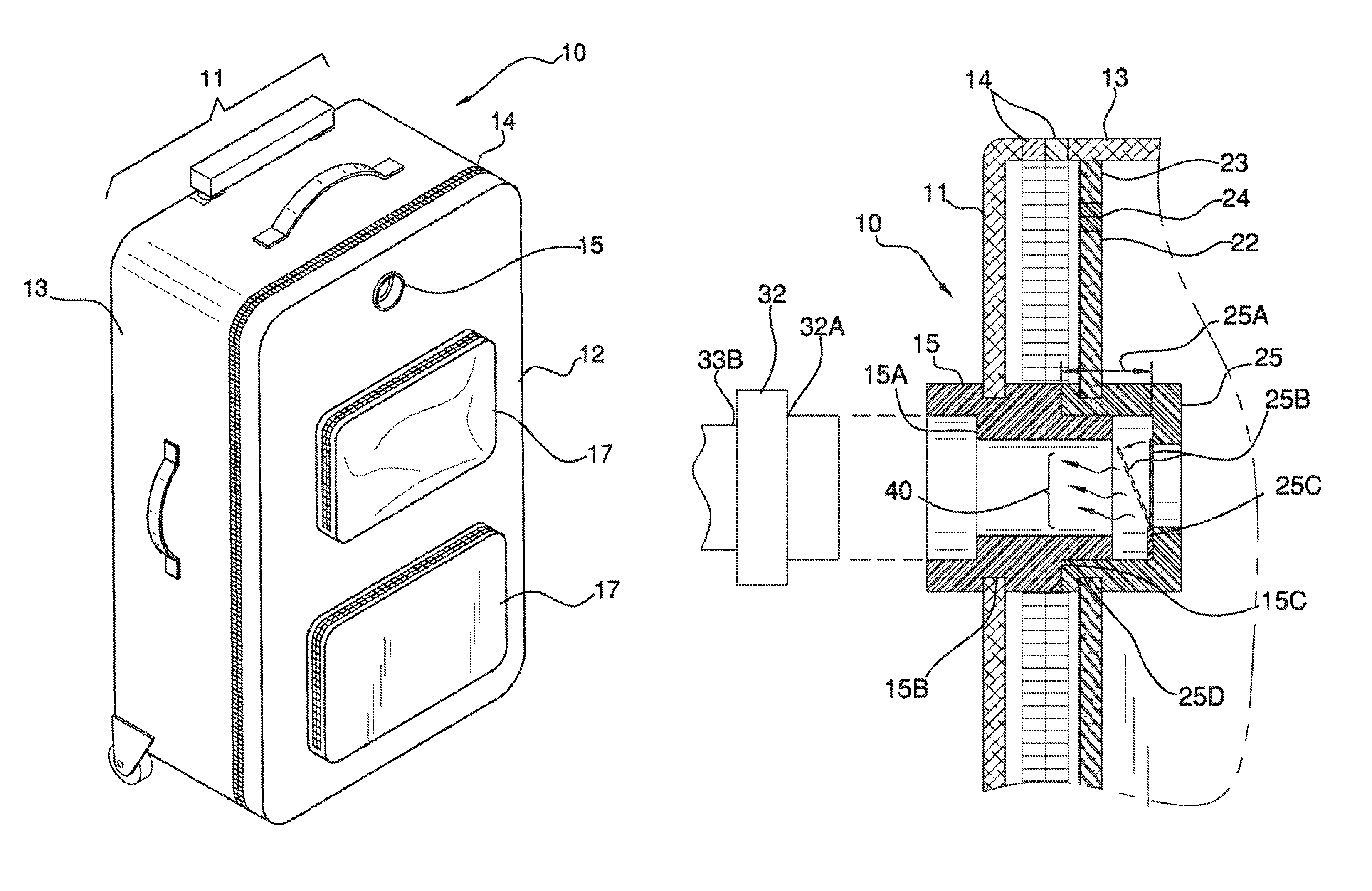
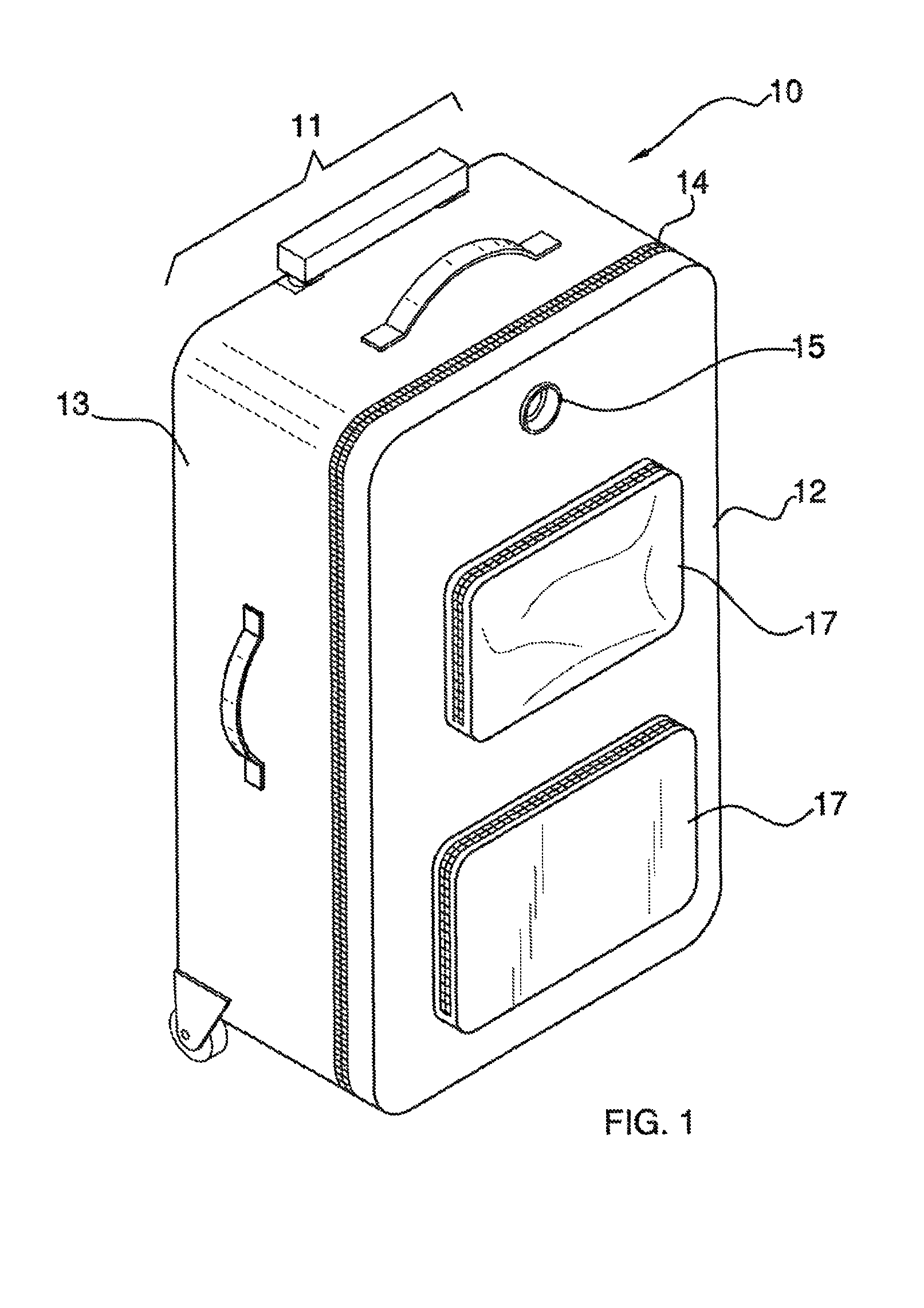
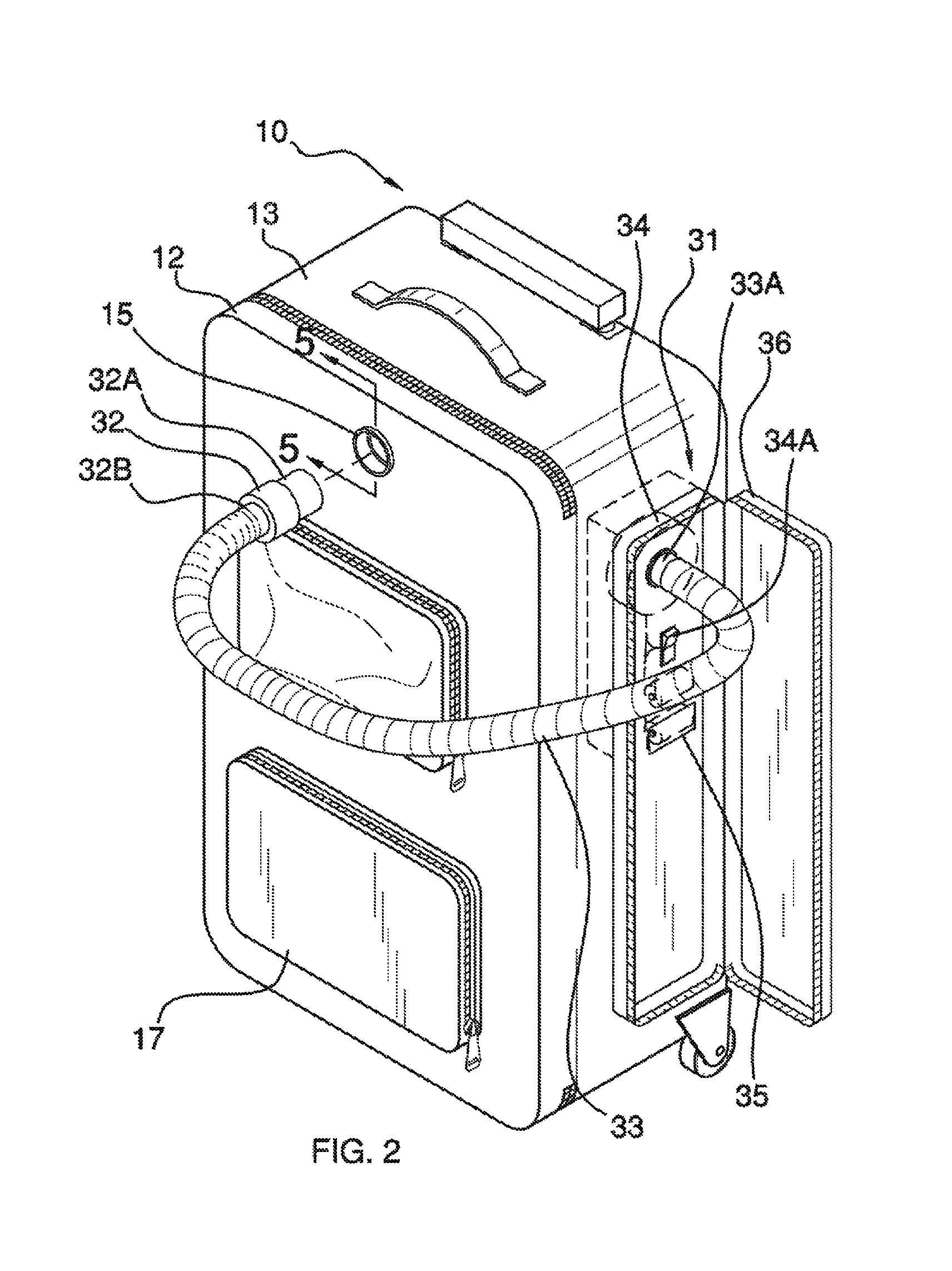
[0016]The luggage with integrated vacuum bags includes a standard piece of luggage that includes at least one vacuum bag within said piece of luggage. The vacuum bags are vacuumed via a vacuuming means integrated on a side of said luggage, which engages a male valve located on an exterior surface of said luggage and of which engages a female valve located on a vacuum bag. The vacuum bags are filled with items typically associated with luggage (garments, etc.) in anticipation of vacuuming, which increases the packing efficiency of the luggage such that more items may be packed into said luggage than when compared with luggage excluding said vacuum bags. The vacuuming means includes a hose, motor, and powering means and vacuums the vacuum bag(s) from outside of said luggage.
[0017]An object of the invention is to provide a piece of luggage with at least one vacuum bag integrated into the design of the luggage such that the vacuum bag is vacuumed from an exterior of said luggage, and with the intent of improving the packing efficiency of the luggage.

Problems solved by technology

However, the insert is not designed to increase packing efficiency or include valves located on a liner and exterior surface that enable a vacuum bag to be deflated therein.
However, the suitcase collapses in overall size to enable storage efficiency of the suitcase and not packing efficiency of items contained within during use.

Method used


Image

  • Luggage with integrated vacuum bags
  • Luggage with integrated vacuum bags
  • Luggage with integrated vacuum bags

Examples


Embodiment Construction

[0031]The following detailed description is merely exemplary in nature and is not intended to limit the described embodiments of the application and uses of the described embodiments. As used herein, the word “exemplary” or “illustrative” means “serving as an example, instance, or illustration.” Any implementation described herein as “exemplary” or “illustrative” is not necessarily to be construed as preferred or advantageous over other implementations. All of the implementations described below are exemplary implementations provided to enable persons skilled in the art to practice the disclosure and are not intended to limit the scope of the appended claims. Furthermore, there is no intention to be bound by any expressed or implied theory presented in the preceding technical field, background, brief summary or the following detailed description.

[0032]Detailed reference will now be made to the preferred embodiment of the present invention, examples of which are illustrated in FIGS. ...


PUM


Abstract

The luggage with integrated vacuum bags includes a standard piece of luggage that includes at least one vacuum bag within said piece of luggage. The vacuum bags are vacuumed via a vacuuming means integrated on a side of said luggage, which engages a male valve located on an exterior surface of said luggage and of which engages a female valve located on a vacuum bag. The vacuum bags are filled with items typically associated with luggage (garments, etc.) in anticipation of vacuuming, which increases the packing efficiency of the luggage such that more items may be packed into said luggage than when compared with luggage excluding said vacuum bags. The vacuuming means includes a hose, motor, and powering means and vacuums the vacuum bag(s) from outside of said luggage.

Description

CROSS REFERENCES TO RELATED APPLICATIONS[0001]Not ApplicableSTATEMENT REGARDING FEDERALLY SPONSORED RESEARCH[0002]Not ApplicableREFERENCE TO APPENDIX[0003]Not ApplicableBACKGROUND OF THE INVENTION[0004]A. Field of the Invention[0005]The present invention relates to the field of luggage, more specifically, a piece of luggage that features vacuum bags integrated therein and of which save space inside of the luggage.[0006]B. Discussion of the Prior Art[0007]As will be discussed immediately below, no prior art discloses a piece of luggage having an integrated vacuum bag storage system that increases packing efficiency within said piece of luggage; wherein at least one vacuum bag is located within said piece of luggage and of which is vacuumed via a vacuuming means located on a side of said luggage which engages a male valve located on an exterior of said luggage, which marries to a female valve located on a vacuum bag located within said luggage.[0008]The Anthony Patent (U.S. Pat. No. 6...

Claims


Application Information

Patent Timeline
Patent Type & Authority Patents(United States)
IPC IPC(8): A45C13/00
CPCA45C13/02A45C2013/028
Inventor EFRON, CHAD
Owner EFRON CHAD
Why Eureka
Try Eureka