Light source device with microwave power source and projection type display apparatus having the same

a technology of display apparatus and light source device, which is applied in the direction of lighting and heating apparatus, magnetic discharge control, instruments, etc., can solve the problems of increasing the number of components, difficult adjustment or the like of light emitters, etc., and achieves the effect of efficient microwave reception, high flexibility, and convenient positioning

Inactive Publication Date: 2013-06-11
SEIKO EPSON CORP
View PDF14 Cites 0 Cited by
  • Summary
  • Abstract
  • Description
  • Claims
  • Application Information

AI Technical Summary

Benefits of technology

[0008]According to this light source device, the light emitter can emit light by using power supply produced by microwaves generated by the microwave power source and radiated from the central conductor. Moreover, the light emitter is disposed such that the end or other portion of the light emitter is not connected with the central conductor directly or indirectly via another component but spaced from the central conductor. In this case, the light emitter disposed away from the central conductor can be easily positioned in various directions with respect to the central conductor such as in parallel, perpendicularly, and obliquely. Thus, the light emitter can be located with high flexibility. That is, the light emitter of the light source device can be freely and easily positioned in such a location as to efficiently receive microwaves and obtain sufficient power supply effect. Accordingly, the light emitter can receive sufficient power supply and achieve efficient light emission.Application Example 2
[0010]According to this structure, the conductor is a component equipped to concentrate the microwaves radiated from the central conductor for efficient power supply, and thus generates a local intensive electric field at the end of the conductor. This intensive electric field generated on the conductor excites the light emitting component contained in the sealing portion and allows the light emitter to emit light more intensively. That is, the light emitter having the conductor can efficiently emit light by concentration of the microwaves. While the light emitter is only required to have at least one conductor, it is more preferable that the plural conductors are equipped in balance for the sealing portion. When the light emitter is disposed such that the conductor extends in the same direction as the amplitude direction of the microwaves, for example, the light emitter can receive the microwaves more efficiently for light emission. Therefore, in the structure in which the central conductor and the light emitter are spaced from each other, the light emitter can be easily disposed in various positions including the condition and position described in this application example.Application Example 3
[0012]According to this structure, the conductor included in the light emitter is disposed outside the sealing portion and not inserted into the sealing portion. In this case, deterioration of the conductor can be reduced by preventing reaction of the conductor with the light emitting component or the like, for example. Thus, the conductor can be used for a long term. That is, the life of the light emitter can increase. Accordingly, the replacement interval of the light emitter included in the light source device can be prolonged, and thus the troublesome work and the economic burden for the replacement can be reduced.Application Example 4
[0014]According to this structure, the reflector of the light source device reflects the light received from the light emitter to increase the efficiency of using light, and releases the light through the opening. The reflector having a part made of conductive material capable of blocking and reflecting microwaves has a function of preventing microwave leakage to the outside and increasing the power supply effect to the light emitter as well as the function of reflecting light. Thus, the necessity of providing other blocking components such as a light source case for preventing microwave leakage to the outside can be eliminated. Moreover, according to the light source device having the structure in which the conductor and the reflector have electric conduction, electromagnetic waves generated at the time of light emission of the light emitter by using microwaves can be guided to a ground. Thus, electromagnetic wave leakage to the outside can be more effectively avoided.Application Example 5
[0016]According to this structure which includes the optical component constituted by various types of optical lenses or the like, the efficiency of using light can be increased by collimating, converging, or deflecting light, or reducing the light guide distance between the light emitter and the optical component, for example. Thus, the light source device including the optical component can control the emitted light, and increase the degree of freedom in the optical design.Application Example 6
[0018]According to this projection type display apparatus, the light emitter of the light source device mounted on the projection type display apparatus can emit light by using the power supply produced by microwaves generated by the microwave power source and radiated from the central conductor. Moreover, the light emitter is disposed such that the end or other portion of the light emitter is not connected with the central conductor directly or indirectly via another component but spaced from the central conductor. In this case, the light emitter disposed away from the central conductor can be easily positioned in various directions with respect to the central conductor such as in parallel, perpendicularly, and obliquely. Thus, the light emitter can be located with high flexibility. That is, the light emitter of the light source device can be freely and easily positioned in such a location as to efficiently receive microwaves and obtain sufficient power supply effect. Accordingly, the light emitter can receive sufficient power supply and achieve efficient light emission. Thus, the projection type display apparatus including the light source device having this light emitter can project a high-luminance image by the efficient light emission of the light emitter.

Problems solved by technology

According to the technology currently used in this field which connects the light emitter with the central conductor, the posture, position and others of the disposed light emitter are almost fixed, and thus adjustment or the like of the light emitter is difficult.
Moreover, the necessity of equipping the light source case covering the light emitter and the reflector for blocking microwave leakage to the outside increases the number of components.

Method used


Image

  • Light source device with microwave power source and projection type display apparatus having the same
  • Light source device with microwave power source and projection type display apparatus having the same
  • Light source device with microwave power source and projection type display apparatus having the same

Examples


first embodiment

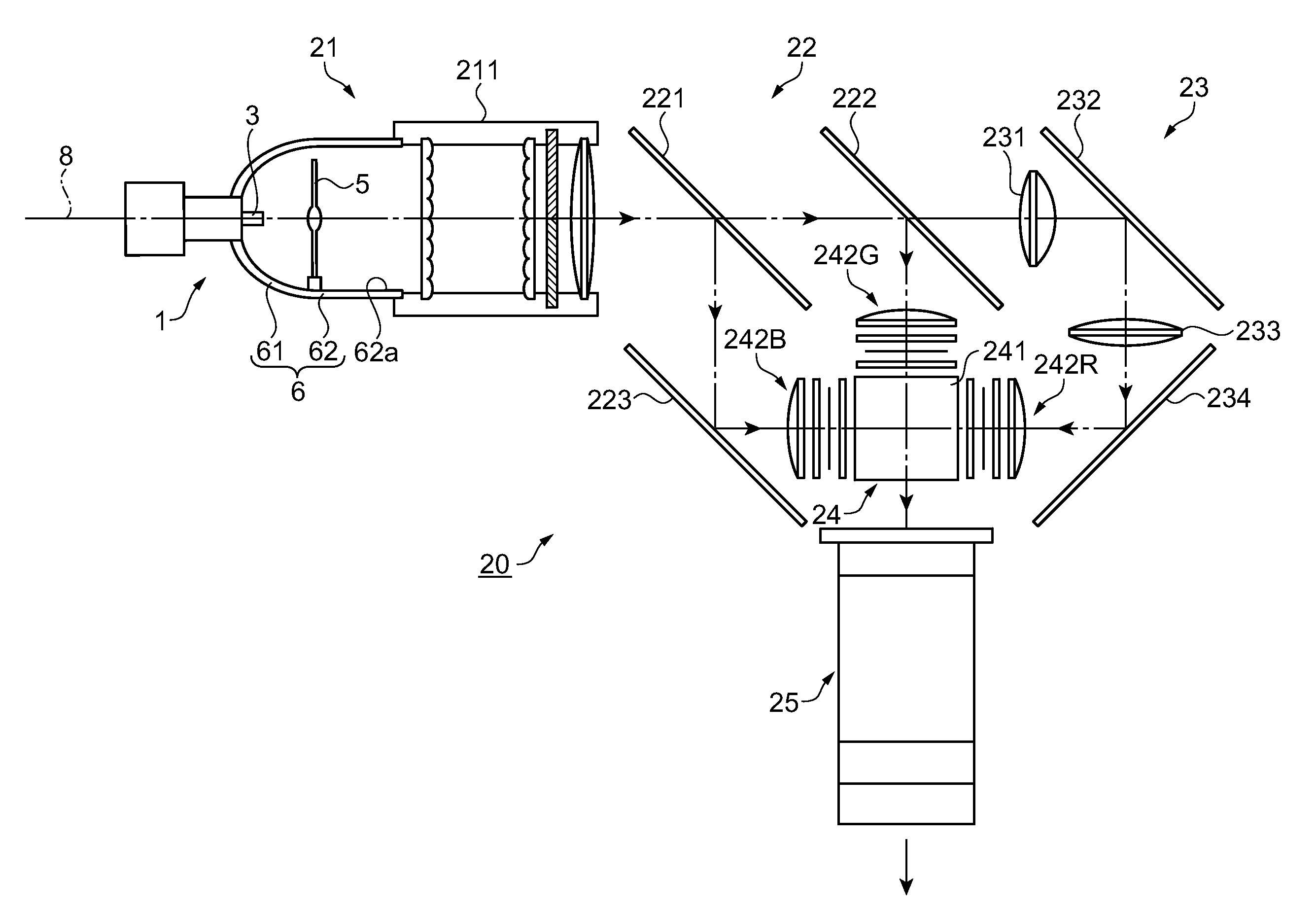
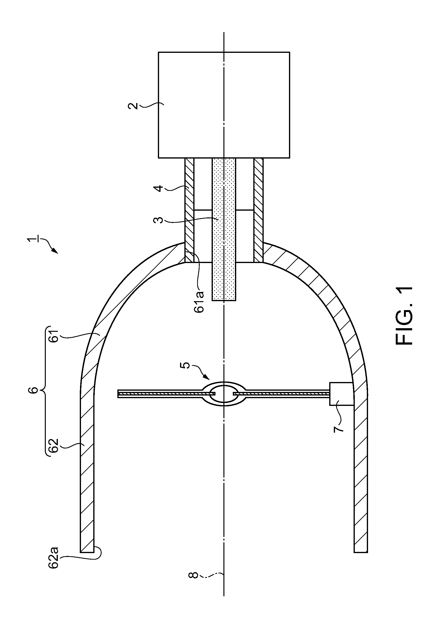
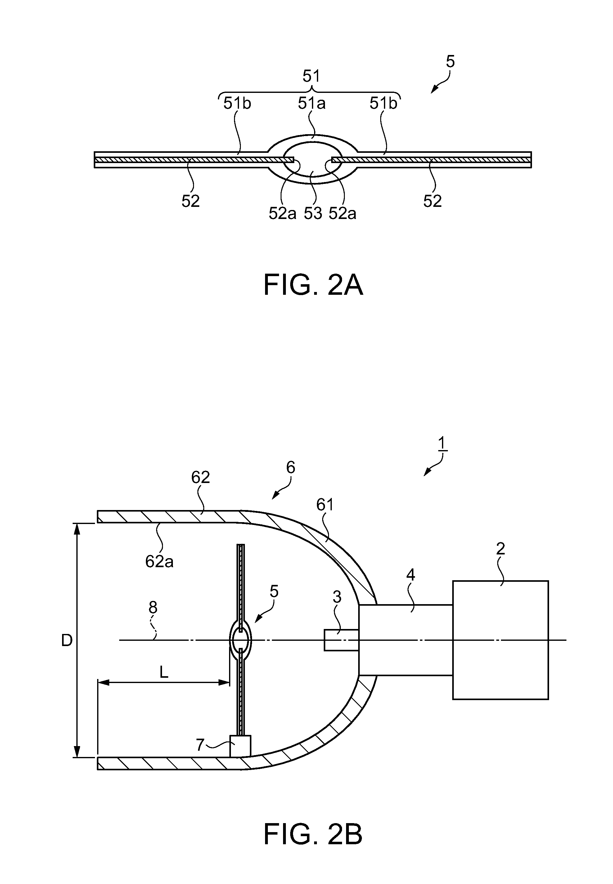
[0027]FIG. 1 is a cross-sectional view illustrating the structure of a light source device according to a first embodiment. As illustrated in FIG. 1, a light source device 1 includes a microwave power source 2 which generates microwaves, a central conductor 3 extended from the interior of the microwave power source 2 to radiate the microwaves generated by the microwave power source 2, a coaxial pipe 4 which accommodates the central conductor 3 as an inside conductor, a discharge lamp (light emitter) 5 disposed on the side opposite to the microwave power source 2 with respect to the central conductor 3 to emit light by power supply produced by the microwaves radiated from the central conductor 3, a reflector 6 which has an opening (aperture) 62a at one end to reflect lights received from the discharge lamp 5 disposed inside the reflector 6 toward the opening 62a, and a holding member 7 which holds the discharge lamp 5 on the reflector 6. The microwave power source 2, the central cond...

second embodiment

[0044]A light source device according to a second embodiment as another example is now described. FIG. 3 is a cross-sectional view illustrating the structure of the light source device in the second embodiment. FIG. 4 is a cross-sectional view illustrating the structure of a discharge lamp in the second embodiment. A light source device 10 according to the second embodiment is different from the light source device 1 in the first embodiment only in the holding structure of a holding member 15 for supporting a discharge lamp 9 in FIG. 3 and the positioning structure for positioning conductors 92 on a sealing portion 91a in FIG. 4. Thus, components of the light source device 10 other than the discharge lamp 9 and the holding member 15 are similar to the corresponding components in the first embodiment, and the same reference numbers are given to the components shown in FIGS. 3 and 4 similar to the corresponding components in the first embodiment. According to the light source device 1...

modified example 1

[0061]According to the light source device 1, each of the conductors 52 of the discharge lamp 5 has one end inserted into the sealing portion 51a, and is insulated from the reflector 6. However, one or both of the conductors 52 of the discharge lamp 5 may have conduction with the reflector 6. The conductor 52 of the discharge lamp 5 is not required to be provided on both sides of the sealing portion 51a but may be disposed only one side of the sealing portion 51a and insulated from the reflector 6. Alternatively, the conductor 52 provided only on one side may have conduction with the reflector 6. As in this example, the structure of the light source device 1 may have a wide variety of options selected according to the shape of the reflector 6, the light emitting substances 53 of the discharge lamp 5 and the like. Accordingly, the light source device 1 having the optimum structure can be produced.


PUM


Abstract

A light source device includes: a microwave power source which generates microwaves; a central conductor which radiates the microwaves; and a light emitter which emits light by receiving the microwaves, wherein the central conductor and the light emitter are spaced from each other.

Description

BACKGROUND[0001]1. Technical Field[0002]The present invention relates to a light source device including a light emitter which emits light by using radiation of microwaves, and a projection type display apparatus containing the light source device.[0003]2. Related Art[0004]As disclosed in JP-A-2008-192392, for example, a light source device of a type currently used includes a microwave generating unit which generates microwaves, a central conductor provided on the microwave generating unit to radiate the microwaves (antenna according to JP-A-2008-192392), a light emitter (discharge lamp) connected with the central conductor to emit lights by power supply produced by the microwaves, a reflector which reflects the lights received from the light emitter in predetermined directions, a chamber formed integrally with the reflector to reflect the microwaves, and a light source case which blocks leakage of the microwaves to the outside. According to the light source device having this struc...

Claims


Application Information

Patent Timeline
Patent Type & Authority Patents(United States)
IPC IPC(8): F21V7/09H01J1/50F21V23/00G03B21/28F21Y101/00
CPCH01J65/044
Inventor KITO, SATOSHISUZUKI, JUNICHIIMAOKA, NORIO
Owner SEIKO EPSON CORP
Why Eureka
Try Eureka