Ram air fan motor cooling

a technology of air fan motor and cooling ram, which is applied in the direction of energy-saving board measures, piston pumps, domestic cooling apparatus, etc., can solve the problems of reducing the performance of the ram air flow system and the limited performance of the electric motor and fan, and achieve the effect of increasing the cooling flow across the ram air fan motor

Active Publication Date: 2013-06-11
HAMILTON SUNDSTRAND CORP
View PDF12 Cites 27 Cited by
  • Summary
  • Abstract
  • Description
  • Claims
  • Application Information

AI Technical Summary

Benefits of technology

[0003]According to one aspect of the invention, a ram air fan assembly includes a ram air fan disposed at a fan inlet and a ram air fan motor operably connected to the ram air fan. A blower is operably connected to the ram air fan and is configured to redirect a cooling flow across the ram air fan motor from a substantially axially directed flow to a substantially radially directed flow thereby increasing the cooling flow across the ram air fan motor.

Problems solved by technology

The flow of cooling air and thus the performance of the electric motor and fan is typically limited by the pressure drop from the heat exchanger inlet to the ram fan inlet.
Such a limitation may result in reduced performance of the ram air flow system.

Method used


Image

  • Ram air fan motor cooling
  • Ram air fan motor cooling
  • Ram air fan motor cooling

Examples


Embodiment Construction

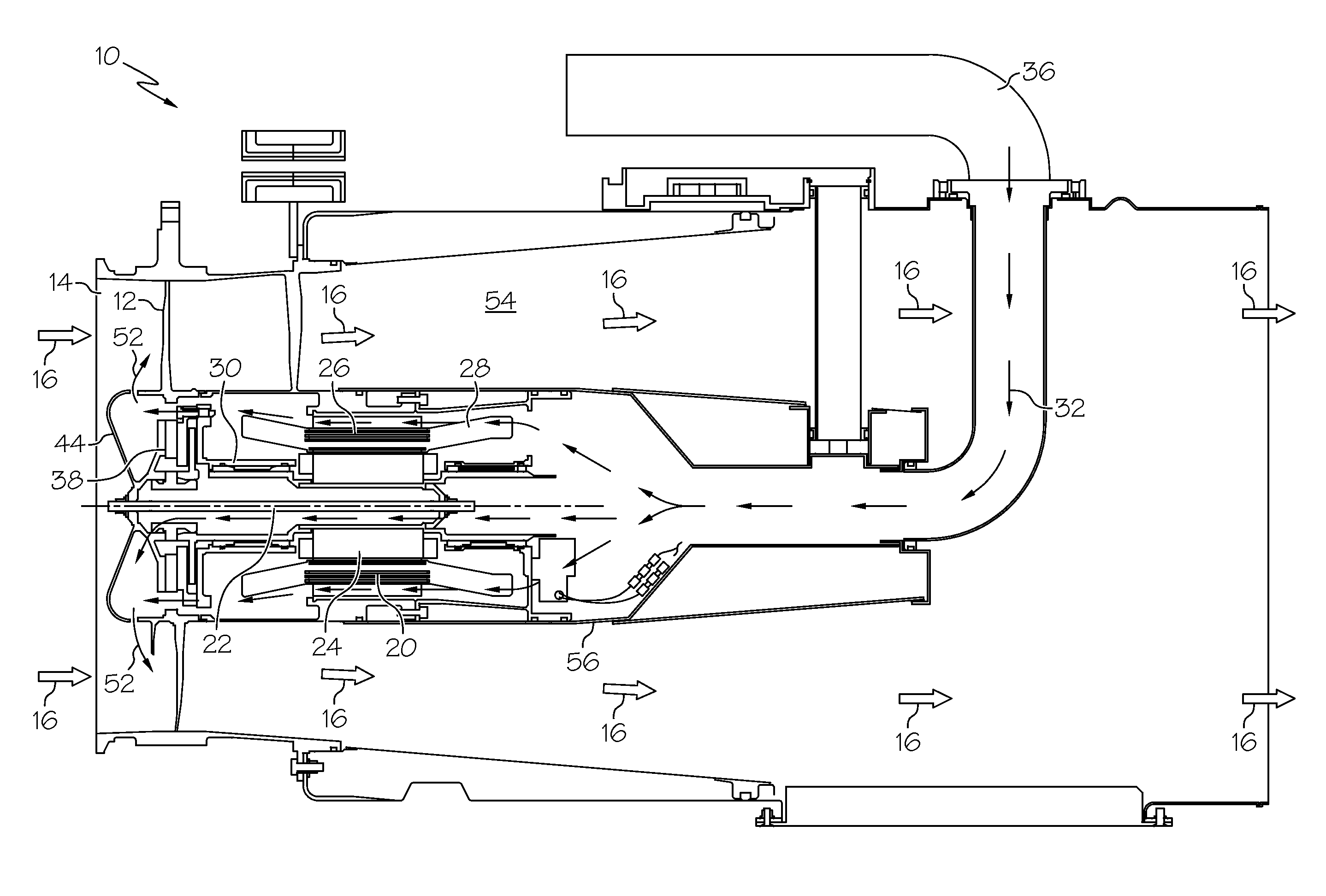
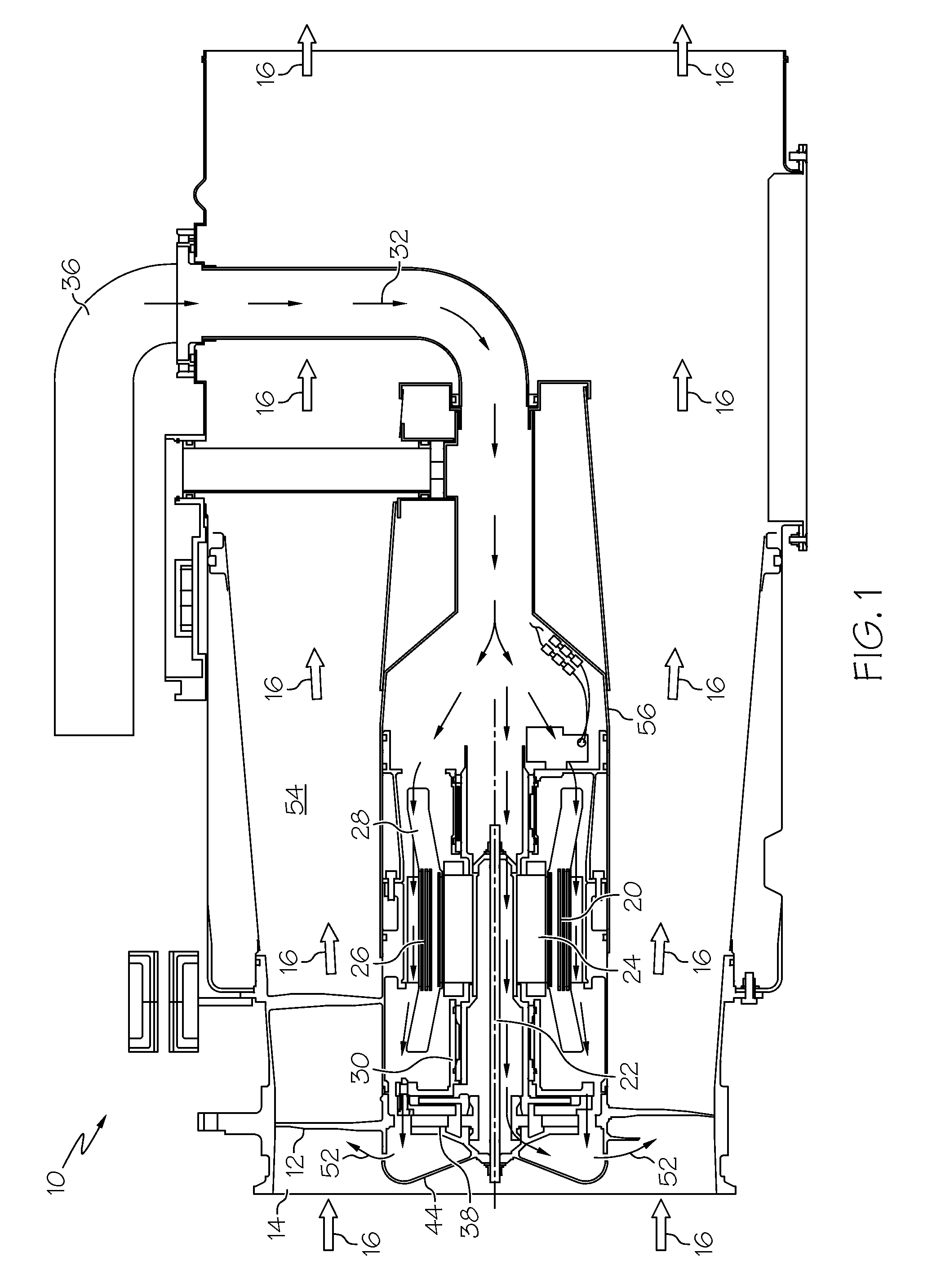
[0008]Shown in FIG. 1 is a view of a ram fan assembly 10 for an aircraft environmental control system (ECS). The ram fan assembly 10 includes a ram air fan (RAF) 12 located at a fan inlet 14. A ram air flow 16 flows into the fan inlet 14 and through a fan passage 54 to a heat exchanger (not depicted) and / or overboard.

[0009]The RAF 12 is operably connected to an RAF motor 20 via an RAF shaft 22. The RAF motor 20, located in a motor housing 56, is an electric motor having a rotor 24 rotably located at the RAF shaft 22, and a stator 26 having a plurality of stator windings 28 disposed radially outboard of the rotor 24. The RAF motor 20 also includes one or more bearings 30 disposed at the RAF shaft 22. The RAF 12 and RAF motor 20 are typically utilized to urge additional air flow 16 through the fan inlet 14 when natural airflow 16 into the fan inlet 14 is not sufficient to meet the requirements of the aircraft. To prevent overheating of the RAF motor 20, particularly the stator winding...


PUM


Abstract

A ram air fan assembly includes a ram air fan disposed at a fan inlet and a ram air fan motor operably connected to the ram air fan. A blower is operably connected to the ram air fan and is configured to redirect a cooling flow across the ram air fan motor from a substantially axially directed flow to a substantially radially directed flow thereby increasing the cooling flow across the ram air fan motor. A method of cooling a ram air fan assembly includes urging a cooling flow toward the ram air fan motor and is directed across the ram air fan motor thus removing thermal energy from the ram air fan motor. The cooling flow proceeds across a blower operably connected to the ram air fan motor, thus directing the cooling flow substantially radially outwardly toward the fan inlet.

Description

BACKGROUND OF THE INVENTION[0001]The subject matter disclosed herein relates to aircraft environmental control. More specifically, the subject disclosure relates to cooling of a ram air fan motor for an aircraft environmental control system.[0002]Many types of aircraft use ram air flow for various purposes, such as in cooling systems for the aircraft. For example, the ram air flow may be utilized to remove heat from various aircraft lubrication and electrical systems and / or used to condition aircraft cabin air. When the aircraft is in flight, the movement of the aircraft creates a sufficient source of ram air flow which can be used for the purposes described above. When the aircraft is on the ground or is operating at low speeds, however, a fan is typically utilized to increase air flow to the cooling systems. Such a fan is driven by an electric motor which, in turn, must be cooled by air flowing across it. Cooling flow is drawn at a heat exchanger inlet and across the electric moto...

Claims


Application Information

Patent Timeline
Patent Type & Authority Patents(United States)
IPC IPC(8): F04B39/06
CPCB64D13/00F04D25/082B64D2013/0644Y02T50/56F04D19/00F04D25/06F04D29/5806Y02T50/50
Inventor HIPSKY, HAROLD W.COLSON, DARRYL A.
Owner HAMILTON SUNDSTRAND CORP
Why Eureka
Try Eureka