Multiple-input-multiple-output antenna device

a multi-input, multi-output technology, applied in the direction of antennas, electrical equipment, radio transmission, etc., can solve the problems of inability to achieve maximum data rates between 450 mbps and 600 mbps, the conventional smart array antenna system cannot utilize the multiple-input-multiple-output (mimo) technique for increasing throughput, and the printed dipole antenna unit of the smart array antenna system to be unable to operate independently. , to achieve the effect of high

Active Publication Date: 2013-06-11
LITE ON TECH CORP
View PDF2 Cites 4 Cited by
  • Summary
  • Abstract
  • Description
  • Claims
  • Application Information

AI Technical Summary

Benefits of technology

[0007]Therefore, an object of the present invention is to provide a Multiple-Input-Multiple-Output (MIMO) antenna device with high directivity, high throughput, and multi-operation bands.
[0008]According to one aspect, a MIMO antenna device of the present invention is adapted for connecting electrically to a radio frequency (RF) circuit so as to transmit and receive RF signals. The MIMO antenna device includes a circuit board, a number (N) of antenna units, a (1×M)-multiplexer unit, and a (1×(N−M))-multiplexer unit. (N) is an integer not smaller than 5, and (M) is an integer that is not smaller than 2 and that is smaller than (N−1). The circuit board has a peripheral edge. The (N) antenna units are disposed on the circuit board proximate to the peripheral edge of the circuit board, and are arranged in a loop formation. The (1×M)-multiplexer unit is disposed on the circuit board, is connected electrically to (M) corresponding ones of the (N) antenna units, and is operable to select one of the (M) corresponding ones of the antenna units for connecting electrically the selected one of the antenna units to the RF circuit. The (1×(N−M))-multiplexer unit is disposed on the circuit board, is connected electrically to remaining (N−M) corresponding ones of the (N) antenna units, and is operable to select one of the (N−M) corresponding ones of the antenna units for connecting electrically the selected one of the antenna units to the RF circuit. Thus, by causing two of the (N) antenna units to operate independently, the MIMO antenna device is able to utilize the MIMO technique so as to achieve high data rate and antenna radiation beamforming.
[0009]Preferably, the circuit board has a ground plane (e.g., a grounding unit). The (N) antenna units are disposed to surround the ground plane, are one-wavelength loop antennas having a balanced structure, and are operable to suppress excited surface currents of the ground plane such that the ground plane acts as a reflector for improving radiation directivity and gain of radiation patterns of each of the antenna units.
[0018]Through disposing the antenna units on the circuit board, arranging the antenna units in a loop formation, and connecting electrically each of the antenna units to a respective one of the multiplexer units, each of the multiplexer units is operable to select one of the corresponding ones of the antenna units for connecting electrically the selected one of the corresponding ones of the antenna units to the RF circuit. Hence, the RF circuit is able to transmit and receive RF signals via at least two independently operating antenna units so as to utilize the MIMO technique such that wireless broadband access points or wireless routers employing the MIMO antenna device of the present invention is capable of achieving high directivity, high throughput, and antenna radiation beamforming.

Problems solved by technology

Such arrangement of the smart array antenna system, the network, and the RF port causes the printed dipole antenna units of the smart array antenna system to be unable to operate independently.
The conventional smart array antenna systems are therefore unable to achieve maximum data rates between 450 Mbps and 600 Mbps (802.11n standard), and only conform to the specifications of the 802.11a / b / g standards.
Consequently, wireless access points or wireless routers that employ the conventional smart array antenna systems cannot utilize the Multiple-Input-Multiple-Output (MIMO) technique for increased throughput.

Method used


Image

  • Multiple-input-multiple-output antenna device
  • Multiple-input-multiple-output antenna device
  • Multiple-input-multiple-output antenna device

Examples


Embodiment Construction

[0033]Before the present invention is described in greater detail, it should be noted that like elements are denoted by the same reference numerals throughout the disclosure.

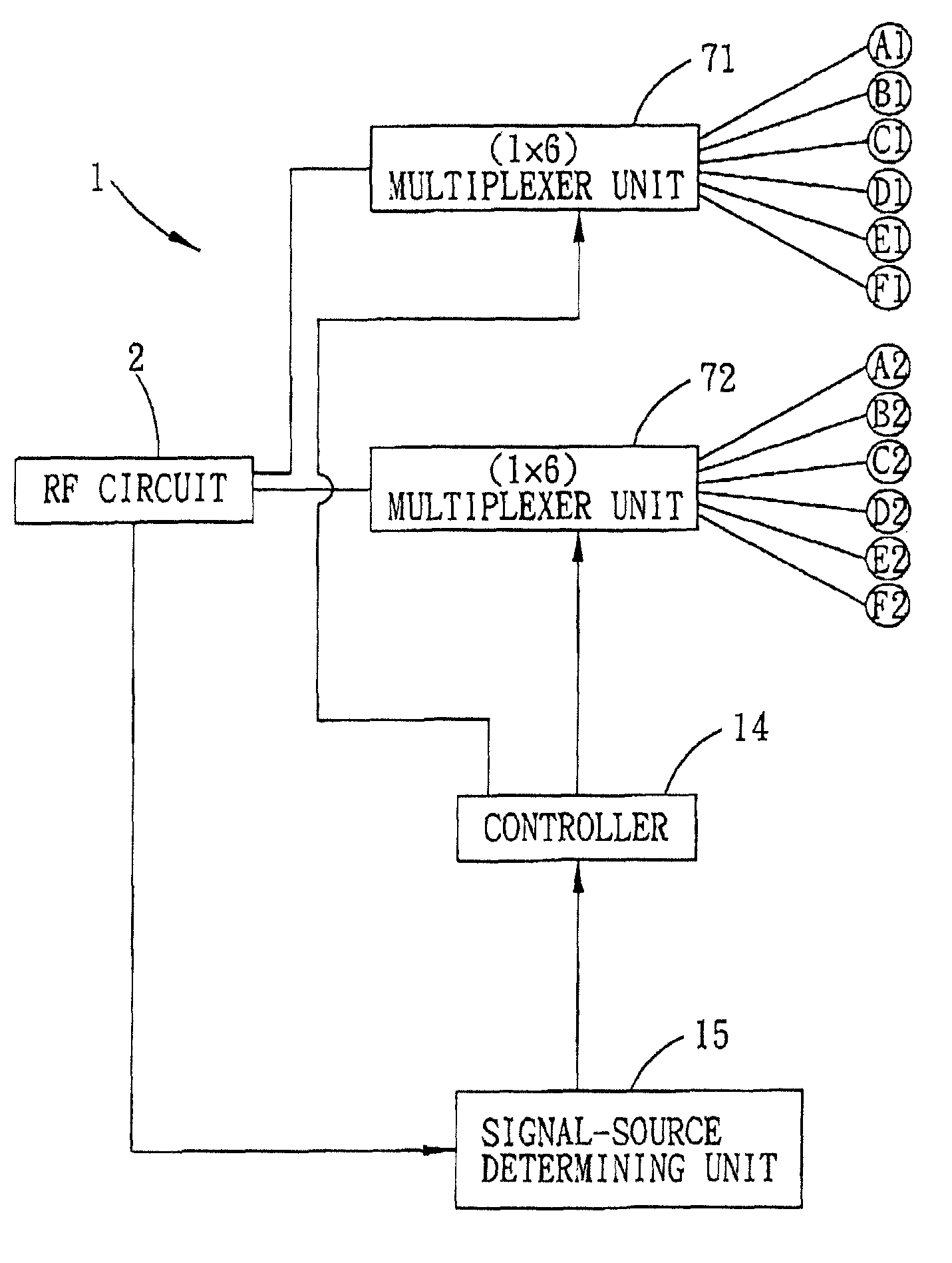
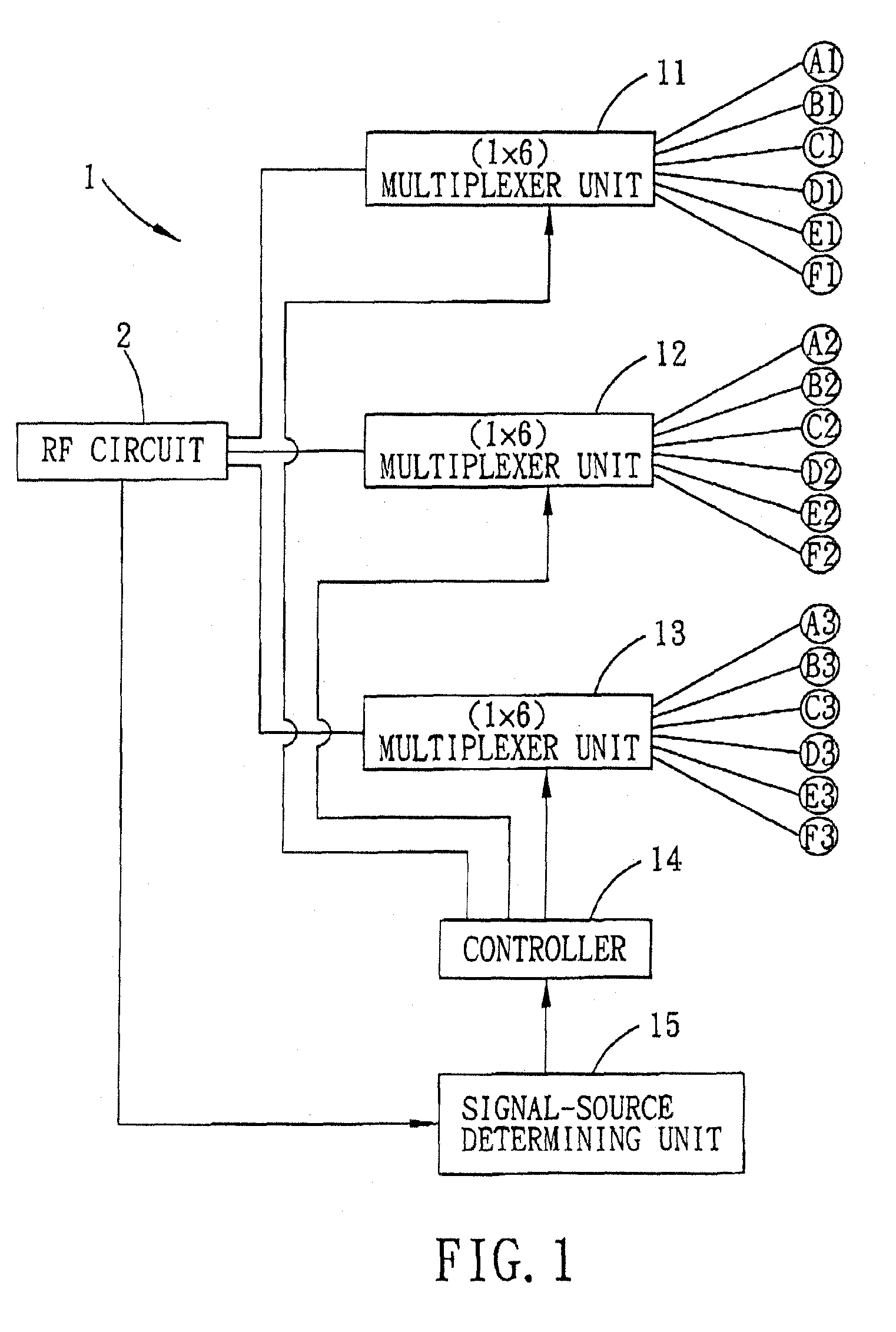
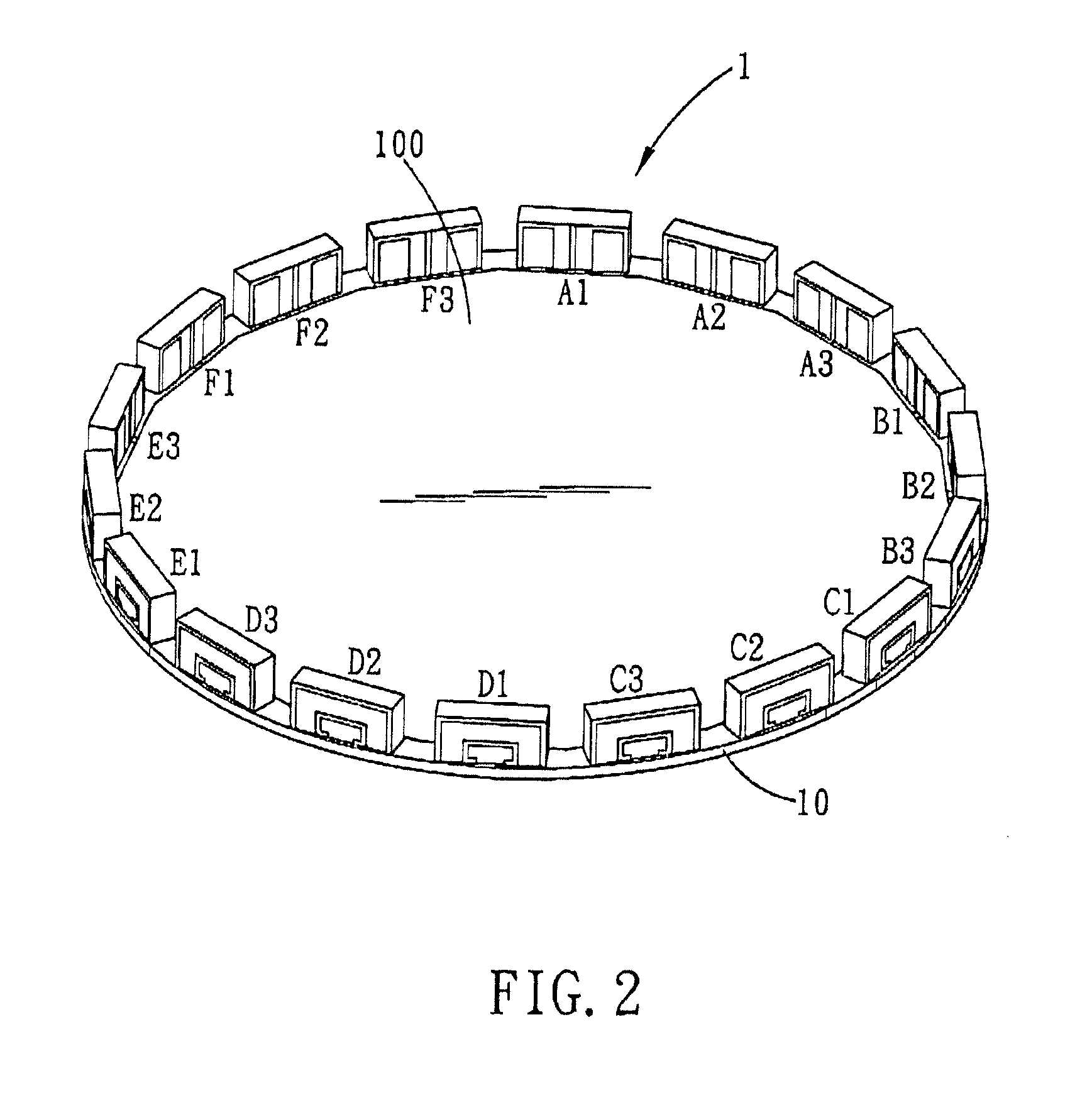
[0034]Referring to FIGS. 1 and 2, the first preferred embodiment of a Multiple-Input-Multiple-Output (MIMO) antenna device 1 according to the present invention is adapted to be connected electrically to a Radio Frequency (RF) circuit 2 for transmitting and receiving RF signals. The MIMO antenna device 1 includes a circuit board 10, a number (N) of antenna units ((N) is an integer not smaller than 6 and is a multiple of 3), and a plurality of (1×(N / 3))-multiplexer units. In the present embodiment, (N) is equal to 18, and the antenna units are divided equally into first, second, and third groups of antenna units (A1-F1), (A2-F2), (A3-F3). Each of the groups of antenna units is connected electrically to a corresponding one of (1×6)-multiplexer units 11, 12, 13.

[0035]The circuit board 10 is a multi-layer board, and ...


PUM


Abstract

A Multiple-Input-Multiple-Output (MIMO) antenna device is adapted for connecting electrically to a radio frequency (RF) circuit for transmitting and receiving RF signals. The MIMO antenna device includes a circuit board, a plurality of antenna units, and a plurality of multiplexer units. The antenna units are disposed on the circuit board proximate to a peripheral edge thereof, are arranged in a loop formation, and are divided into a plurality of groups of the antenna units. Each of the multiplexer units is connected electrically to a respective one of the groups of the antenna units for selecting one of the corresponding antenna units and for connecting electrically the selected one of the corresponding antenna units to the RF circuit, thereby achieving the MIMO technique with the independently and simultaneously operating antenna units.

Description

CROSS-REFERENCE TO RELATED APPLICATION[0001]This application claims priority of Chinese Application No. 200910261357.4, filed on Dec. 22, 2009.BACKGROUND OF THE INVENTION[0002]1. Field of the Invention[0003]The present invention relates to an antenna device, more particularly to Multiple-Input-Multiple-Output (MIMO) antenna device.[0004]2. Description of the Related Art[0005]U.S. Patent Application Publication Nos. 20060109067 and 20060192720 disclose two conventional smart array antenna systems, each of which includes a plurality of printed dipole antenna units that are large in dimensions and that are coupled to a single Radio Frequency (RF) port via a network comprising transmission cables, phase shifters, and power dividers. Such arrangement of the smart array antenna system, the network, and the RF port causes the printed dipole antenna units of the smart array antenna system to be unable to operate independently. The conventional smart array antenna systems are therefore unabl...

Claims


Application Information

Patent Timeline
Patent Type & Authority Patents(United States)
IPC IPC(8): H04B1/18
CPCH01Q3/242H01Q21/205H01Q21/28H04B7/0413H04B7/0452
Inventor SU, SAOU-WENTSAI, LIN-HANCHEN, CHUAN-HSING
Owner LITE ON TECH CORP
Why Eureka
Try Eureka