Linear motion guide unit

a technology of motion guide unit and guide rod, which is applied in the direction of linear bearings, shafts and bearings, bearings, etc., can solve the problems of high working cost, high working cost, and high difficulty in high precision, and achieves reduced machining costs, easy and simple finishing, and the effect of working process

Active Publication Date: 2013-06-18
NIPPON THOMPSON
View PDF11 Cites 3 Cited by
  • Summary
  • Abstract
  • Description
  • Claims
  • Application Information

AI Technical Summary

Benefits of technology

[0007]The present invention has for its primary object to overcome the major challenges as stated earlier, and to provide a linear motion guide unit adapted to be used between tow parts which slide relative to each other for linear reciprocating mechanism built in semiconductor fabricating equipment, machine tools, industrial robots, and so on. More particularly, the present invention is envisaged rendering machining process on a carriage of the slider easier or simpler to make machining costs less for the sake of cost reduction for manufacturing the entire linear motion guide unit. To this end, the present invention provides a linear motion guide unit in which return passages for more than one ball serving as the rolling element isn't through-holes made in sidewise opposed bulges of the carriage, but rather tubular members that fit over spigots raised above turnaround passages in end caps to extend closely to the carriage. Moreover, when the tubular members have inside any continuous-cellular or porous compact of sintered resinous material, the present invention may provide the linear motion guide unit which is more preferable for maintenance-free lubrication over a long-lasting period and further for large freedom of design considerations to cope with a variety of desired functions with the help of different structural variations of the tubular members.SUBJECT MATTER TO OVERCOME THE CHALLENGES
[0013]In the present invention, a linear motion guide unit is provided in which the tubular member is composed of an outer cylinder and an inner cylinder placed inside the outer cylinder, the outer cylinder being of a material selected from stainless steel, aluminum alloy, ceramics, resins and a composite reinforced with carbon fibers, and the inner cylinder being of a sintered resinous material of porous texture impregnated with lubricant. Moreover, the outer cylinder having accommodated the inner cylinder therein fits over the spigots at the tube ends thereof in such a relation that circular edges of the inner cylinder come into edge-on abutment against the circular edges of the spigots, and the inner cylinder has a radial thickness equal with that of the spigots so that the turnaround passages are smoothly connected to the return passage with causing no gap or no difference between them. In a further another aspect of the present invention, there is a slight clearance between an inside circular surface of the outer cylinder and an outside circular surface of the inner cylinder.
[0014]In the present invention a linear motion guide unit is provided in which the tubular member has a one-piece construction of a material selected from resins, resinous materials of enhanced stiffness reinforced with carbon fibers and metallic materials. Moreover, the tubular member at the tube ends thereof is larger than at a major middle of the tubular member in inside diameter to fit at the tube ends over the spigots and wherein the tubular member at the major middle is equal with the spigots in the inside diameter so as to connect the turnaround passages with the return passage with causing no gaps or differences between the passages.
[0016]With the linear motion guide unit constructed as stated earlier, there is no need to bore or drill a through-hole in the carriage in preparation for installation of a tubular member in the carriage. Instead, it may be sufficient only to undercut the bulges of the carriage simultaneously with machining phase on the carriage. Thus, the working process for the return passages is easy and simple with accompanying reduced machining costs. The closed or looped circuits through which the rolling elements or balls circulate may be finished easily and simply with just the placement of the tubular members in the concaves which have been made by undercutting the underparts of the first bulges. Cutting away material from the undersides of the first bulges of the carriage, moreover, makes for slim construction or weight reduction of the first bulges, which means the slider, more especially the linear motion guide unit weighs less. As an alternative to the tubular member of monolithic one-piece construction, the tubular member may be composed of an outer cylinder of metals and so on having high strength and inner cylinder accommodated inside the outer cylinder and made of a sintered resinous material of porous texture impregnated with lubricant. The alternative as stated earlier is not only easy in assembly and simple in construction, but also favorable to the enhancement of the strength of the tubular member and further maintenance-free operation for the lubrication.

Problems solved by technology

This means the drilling or boring operation to the carriage 10P wants high precision with difficulties and high working cost.
This involves a problem of high working costs.
Moreover, the joint construction that the tubular members fit into the end caps is apt to cause a specific difficulty in which any gap or difference might come at mating surfaces between the tubular members and the end caps.
This poses a serious challenge that the rolling elements get caught or huddled together to render the sliding performance worse.
In addition, other challenges might be caused in which the rolling elements after having hit against the gap or difference raised excessive wear on either of the tubular members and the end caps, and the rolling elements after having rolled with staggers huddled together, thereby worsening the sliding condition of the slider.

Method used


Image

  • Linear motion guide unit
  • Linear motion guide unit
  • Linear motion guide unit

Examples


Embodiment Construction

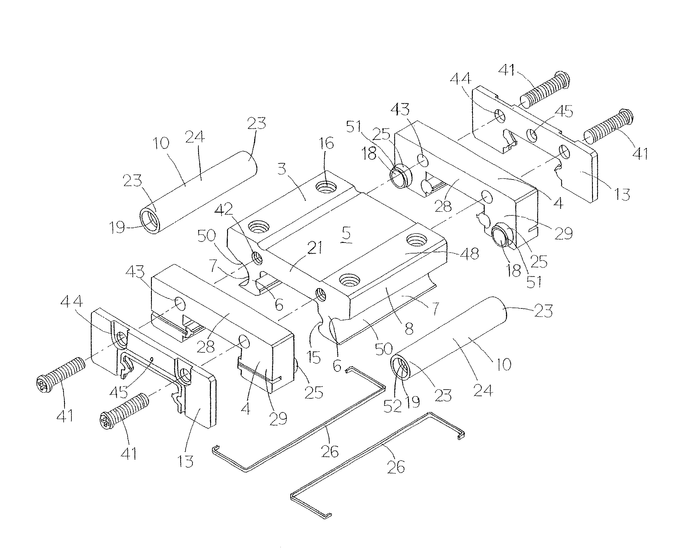
[0026]The linear motion guide unit according to the present invention is adapted for use in any relatively sliding components in machinery as diverse as semiconductor fabricating equipment, robotic machines, machine tools, and so on to realize the relative sliding between parts or components with smoothness. Especially, the linear motion guide unit of the present invention features the return passage which is prepared separately from the carriage instead of fitted in a through-hole drilled or bored in the carriage. Preferred embodiments of the linear motion guide unit constructed according to the present invention will be described in detail by reference to the drawings.

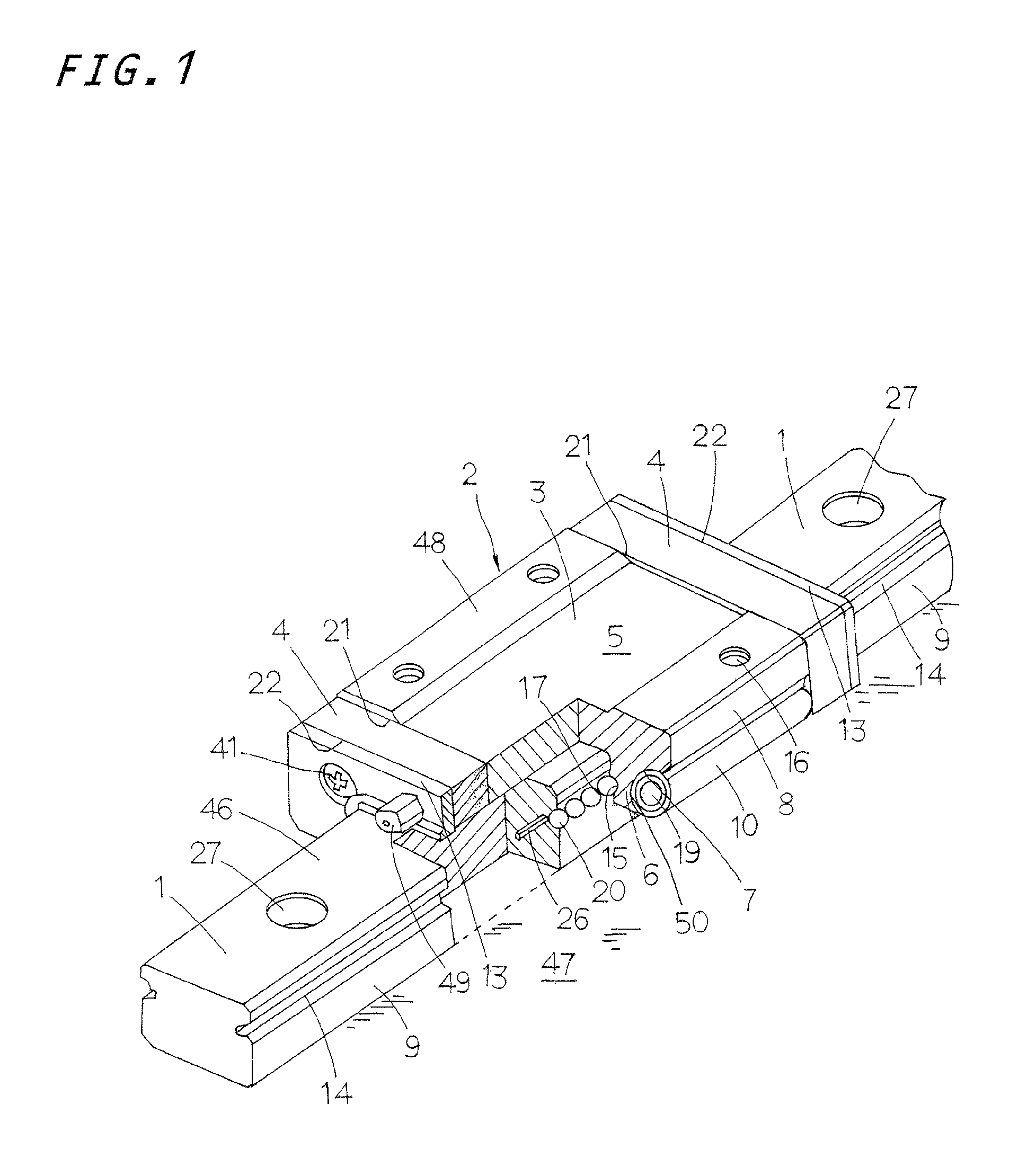
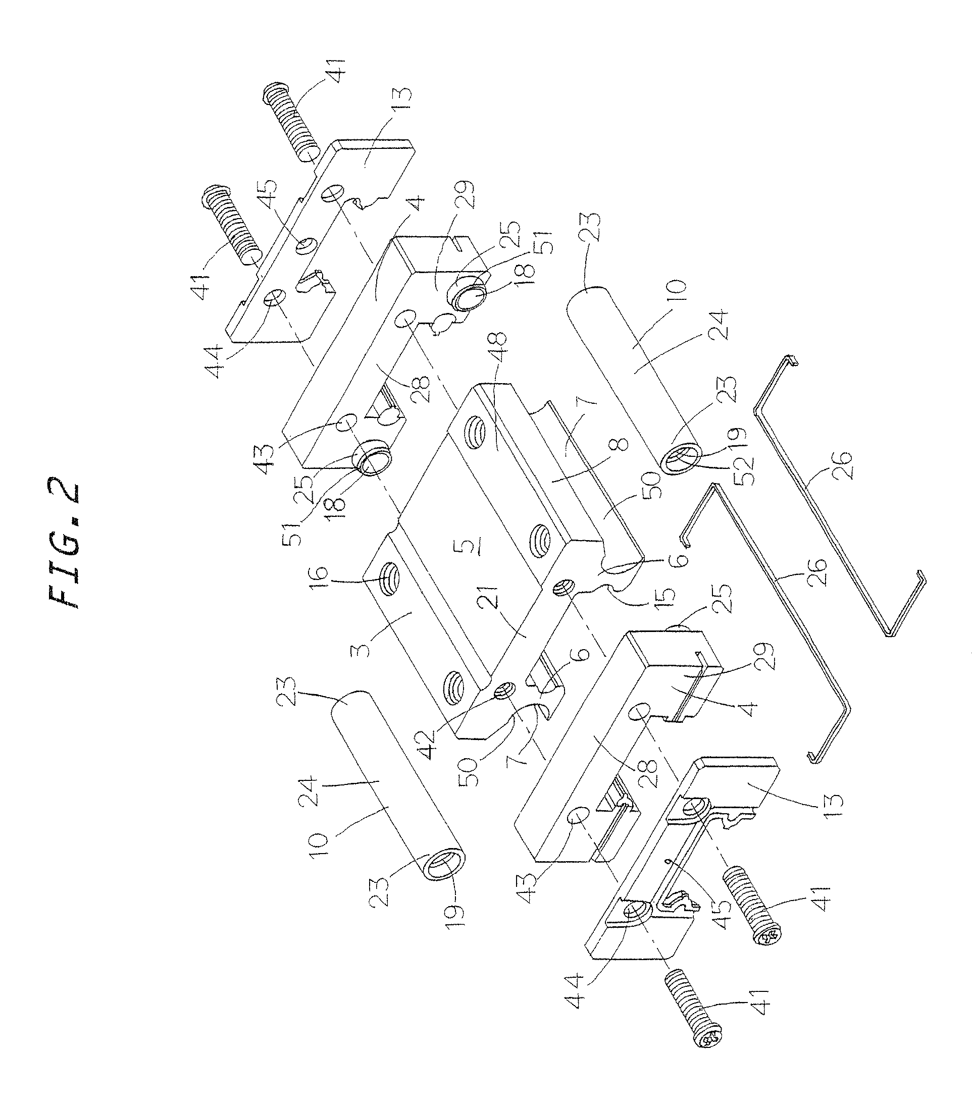
[0027]First, the linear motion guide unit of the present invention will be explained generally with reference to FIGS. 1 and 2. The linear motion guide unit is intended to find the applications between components or members which slide relatively to each other, for example a machine bed and a table, and composed of a...


PUM


Abstract

In a slider of a linear motion guide unit, a carriage in the slider is cut away at undersides thereof to form concaves in which tubular members defining return passages therein are placed. This is in favor of reduced machining cost. The slider is composed of the carriage having an upper portion and side bulges, end caps secured on ends of the carriage, and tubular members installed closely outside the bulges of the carriage in the sliding direction. Sidewise underparts of the carriage is cut away to provide the concaves into which the tubular members fit with tube ends being kept in spigots which communicate with turnaround passages in the end caps.

Description

FIELD OF THE INVENTION[0001]The present invention relates to a linear motion guide unit comprised of an elongated guide rail and a slider designed to move on the elongated guide rail relatively to the guide rail by virtue of a plurality of rolling elements.BACKGROUND OF THE INVENTION[0002]Linear motion guide units have been extensively applied in recent years between tow parts which slide relative to each other for linear reciprocating mechanism used in increased industrial fields including semiconductor fabricating equipment, machine tools, industrial robots, and so on. Most prior linear motion guide units have been ordinarily fed with lubricant every a preselected interval through any oiling port to ensure smooth lubrication for the rolling elements throughout a closed or looped circuit. Recently advanced machines and instruments, however, are increasingly wanted energy saving, simple construction and less production cost, and further in need of making them virtually maintenance-f...

Claims


Application Information

Patent Timeline
Patent Type & Authority Patents(United States)
IPC IPC(8): F16C29/06
CPCF16C29/0611F16C33/6648F16C29/0657
Inventor KONDO, MASATOSHIKUWABARA, HIDEKI
Owner NIPPON THOMPSON
Why Eureka
Try Eureka