Filter

a filter and electrostatic technology, applied in the field of electrostatic filters, can solve the problems of reducing the amount of dust in the electrostatic filter, shortening the life of the electrostatic filter itself and any further downstream filters, and reducing the electrostatic properties, so as to maximize the opportunity for charging and maximize the volume

Inactive Publication Date: 2013-06-18
DYSON TECH LTD
View PDF132 Cites 8 Cited by
  • Summary
  • Abstract
  • Description
  • Claims
  • Application Information

AI Technical Summary

Benefits of technology

[0014]Such an arrangement where the air does not have to flow through the electrodes during use may be advantageous because it may reduce the pressure drop across the electrostatic filter. In addition because the electrodes are non-porous they have a larger surface area than they would if the electrodes were porous. This may improve the overall performance of the electrostatic filter.
[0016]This electrostatic filter uses the potential difference formed across the filter medium to collect dust in the filter medium itself rather than on collector electrodes. This arrangement is advantageous over previous electrostatic filters because there are no collector electrodes to clean. This may reduce the need for maintenance and increase the life of the filter due to the dust retention capacity of the filter medium.
[0017]The potential difference occurs because the electrically resistive filter medium provides a load and therefore only a small current flows through it. However the electric field will disturb the distribution of any positive and negative charges, in the fibers of the electrically resistive filter medium, causing them to align with their respective electrode. This process causes the dust to bond to or settle on the fibers of the filter medium because dust particles in an airstream passing through the filter will be attracted to respective positive and negative ends of the filter medium. This may help to cause the dust particles to be trapped in the filter medium itself without requiring the dust particles to be captured on a charged electrode.
[0018]In addition because the electrostatic filter is essentially one component i.e. the filter medium is located between the first and the second electrodes, it may be more compact than previous arrangements and may therefore be packaged more easily. It may also be possible to locate the electrostatic filter in any airstream of an appliance. This may help to allow the filter to be utilised in a domestic vacuum cleaner.
[0021]The electrostatic filter may also further comprise at least one corona discharge means, the filter medium being arranged downstream of the corona discharge means. Adding a corona discharge means advantageously may increase the efficiency of the electrostatic filter. This is because the corona discharge means helps to charge any dust particles in the airstream before they pass through the filter medium thus helping to increase dust particle attraction to the filter medium.
[0028]Preferably the corona discharge electrode and / or the electrode of low curvature may project upstream from an upstream surface of the filter medium. Ideally the discharge electrode and / or the electrode of low curvature may project below a lower surface or above an upper surface of the filter medium. In a particular embodiment the electrode of low curvature projects both upstream and downstream from a lower surface of the corona discharge electrode. This is advantageous because it helps to maximize the volume over which the ionizing field is generated to maximize the opportunity for charging dust particles as they pass through the ionizing field.

Problems solved by technology

Such electrostatic filters are relatively cheap to produce but suffer from the disadvantage that their charge dissipates over time resulting in a reduction of their electrostatic properties.
This in turn reduces the amount of dust the electrostatic filter can collect which may shorten the life of both the electrostatic filter itself and any further downstream filters.
A disadvantage with this arrangement is that they are relatively inefficient, are made from relatively expensive materials and the collector electrodes require constant maintenance in order to keep them free of collected dust.
Once the collector electrodes are coated in a layer of dust they are much less efficient.
While this arrangement is compact it suffers from the disadvantage that dust collects on the inside of the cyclones.
Not only does this require constant and difficult maintenance removing dust from the walls of the cyclone, but also any dust trapped inside the cyclone will interfere with the cyclonic airflow decreasing the separation efficiency of the cyclone itself.

Method used


Image

  • Filter
  • Filter
  • Filter

Examples


Embodiment Construction

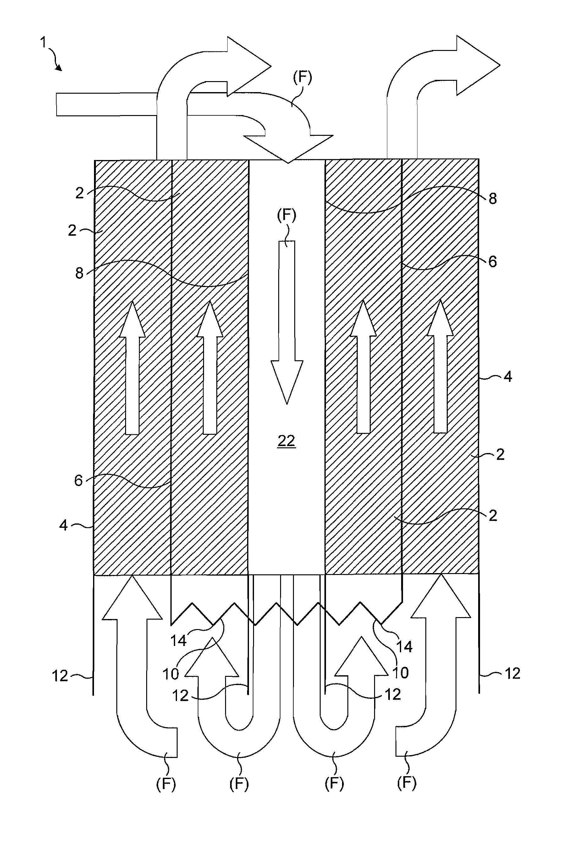
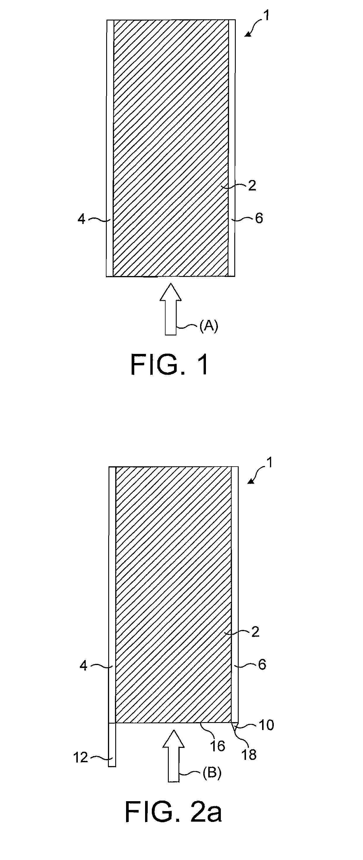
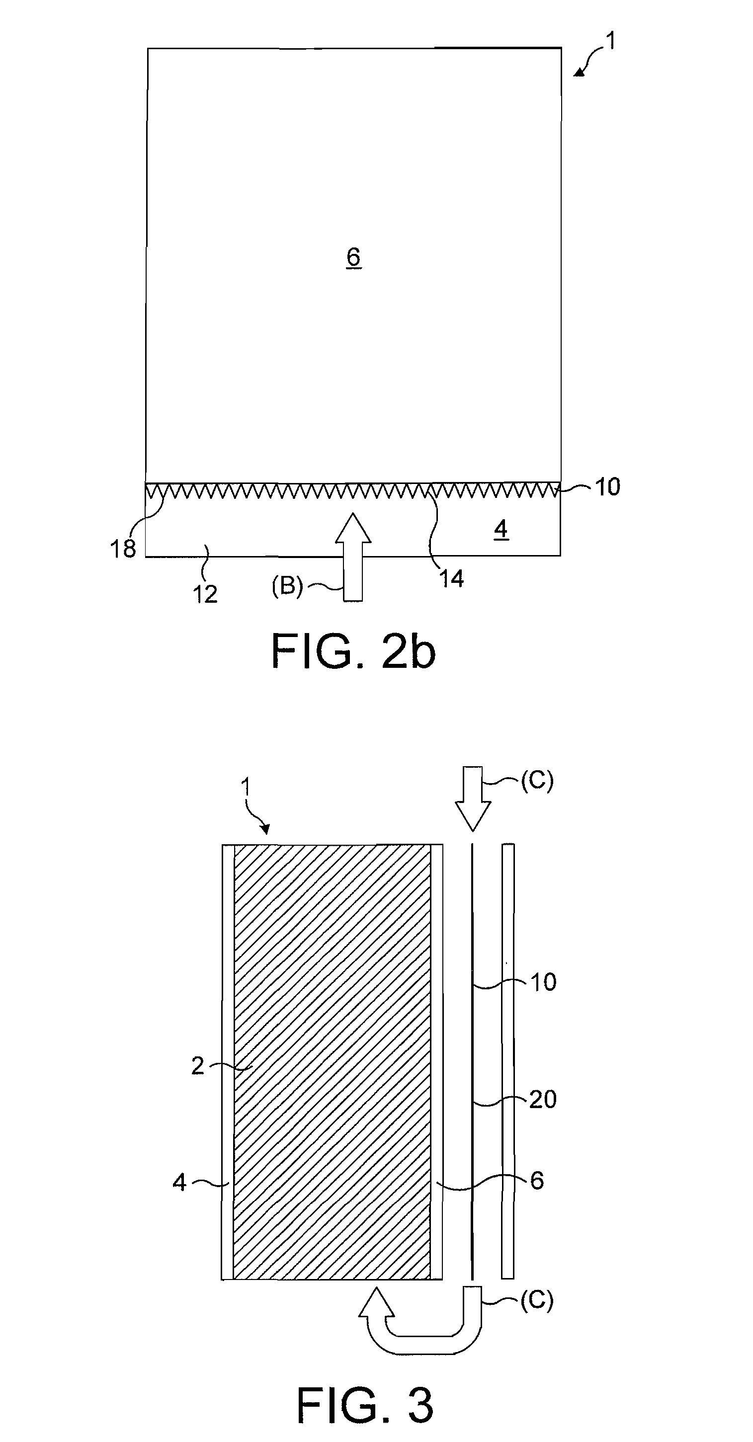
[0063]With reference to FIG. 1 an electrostatic filter is shown and indicated generally by the reference numeral 1.

[0064]It can be seen that the electrostatic filter 1 comprises an electrically resistive filter medium 2 sandwiched between and in contact with a first non-porous electrode electrode 4 and a second non-porous electrode 6. In use the first and second electrodes 4, 6 are each at a different voltage such that a potential difference is formed across the electrically resistive filter medium 2. The first electrode 4 is at 0 Volts and the second electrode 6 is at + / −4 to 10 kV during use. The electrodes 4, 6 are connected to a high voltage power supply (not shown).

[0065]The first and second electrodes 4, 6 form at least part of an air pathway which is filled by the electrically resistive filter medium 2 such that in use dust laden air (A) must pass through the electrically resistive filter medium 2 along the length of the first and second electrodes 4,6. The potential differen...


PUM


Abstract

The present invention relates to an electrostatic filter. Particularly but not exclusively the invention relates to an electrostatic filter for removing dust particles, for example an electrostatic filter for use in a vacuum cleaner, fan or air conditioner. The electrostatic filter includes a filter medium located between a first and a second electrode, each at a different voltage during use, such that a potential difference is formed across the filter medium, the first and second electrodes being substantially non-porous.

Description

REFERENCE TO RELATED APPLICATIONS[0001]This application claims the priority of United Kingdom Application No. 0912936.2, filed Jul. 24, 2009, the entire contents of which are incorporated herein by reference.FIELD OF THE INVENTION[0002]The present invention relates to an electrostatic filter. Particularly, but not exclusively the invention relates to an electrostatic filter for removing dust particles from an airstream, for example an electrostatic filter for use in a vacuum cleaner, fan or air conditioner.BACKGROUND OF THE INVENTION[0003]It is well known to separate particles, such as dirt and dust particles from a fluid flow using mechanical filters, such as foam filters, cyclonic separators and electrostatic separators where dust particles are charged and then attracted to another oppositely charged surface for collection.[0004]Known cyclonic separating apparatus include those used in vacuum cleaners. Such cyclonic separating apparatus are known to comprise a low efficiency cyclo...

Claims


Application Information

Patent Timeline
Patent Type & Authority Patents(United States)
IPC IPC(8): B03C3/155
CPCA47L9/10A47L9/12B03C3/30B03C3/025B03C3/155B03C3/017B03C3/41B03C3/15B01D35/06B01D46/42B01D46/50
Inventor HORNE, LUCAS
Owner DYSON TECH LTD
Why Eureka
Try Eureka