Moment resistant building column insert system and method

a technology of building columns and inserts, applied in the direction of girders, branching pipes, mechanical equipment, etc., can solve the problems of high stress on joints, large columns, and difficult process, and achieve the effect of reducing the number of times of inserts

Inactive Publication Date: 2013-06-25
VAUGHN WILLAIM B
View PDF46 Cites 38 Cited by
  • Summary
  • Abstract
  • Description
  • Claims
  • Application Information

AI Technical Summary

Benefits of technology

[0028]Some key advantages of the invention are in simplifying the assembly of multiple beams to a building column with the use of the insert and the erection connector, thus saving time and costs. Another advantage is the added strength to the building column by the insert column or insert plate, where the insert distributes the beam loads along the length of the building column. The building column insert is provided as an insert that has insert connectors and connector covers encased in hardened filler, where the filler has through holes aligned with the insert through holes. The insert with hardened filler eliminates the need for pouring and curing grout for the entire column prior to pre-tensioning the mounting bolts. The insert can be lowered into a building column via a positioning element, and the insert hole pattern is aligned with the building column hole pattern, where the insert can be held by a hoist for assembly or the insert can be secured to the column using screws applied from outside of the column or it can be welded, for example. A further advantage of the invention, is the system enables simple and robust splicing of building columns in a cost effective manner.
[0029]The objectives and advantages of the present invention will be understood by reading the following detailed description in conjunction with the drawing, in which:
[0030]FIG. 1 shows an exploded perspective view of a moment resistant building column insert system according to the present invention.
[0031]FIGS. 2(a)-2(d) show some embodiments of the erection insert according to the present invention.
[0032]FIGS. 3(a)-3(d) show some variations of the threaded element 110 with the insert according to the present invention.
[0033]FIGS. 4(a), 4(b) show perspective views of the moment resistant building column insert system according to the present invention.

Problems solved by technology

As a result, the joints can become highly stressed during a seismic event.
This is a problem for “I” section columns in that much larger columns would be required to resist weak axis loads.
However, the HSS column presents a challenge in another way from the typical “I” section column in making the moment-resisting connection between the beam and the column.
A problem arises when assembling the beams to the columns where multiple beams and columns are required.
This process could be slow, difficult, expensive or very impractical.
(U.S. Pat. No. 5,012,622) teach a solid concrete core thrust into a column, which then disallows the use through-bolt assembly and necessitates a clamping assembly that has limited utility.
These and other designs and systems have been used to make this connection but they are considered costly, less flexible or impracticable to build.

Method used


Image

  • Moment resistant building column insert system and method
  • Moment resistant building column insert system and method
  • Moment resistant building column insert system and method

Examples


Embodiment Construction

[0038]Although the following detailed description contains many specifics for the purposes of illustration, anyone of ordinary skill in the art will readily appreciate that many variations and alterations to the following exemplary details are within the scope of the invention. Accordingly, the following preferred embodiment of the invention is set forth without any loss of generality to, and without imposing limitations upon, the claimed invention.

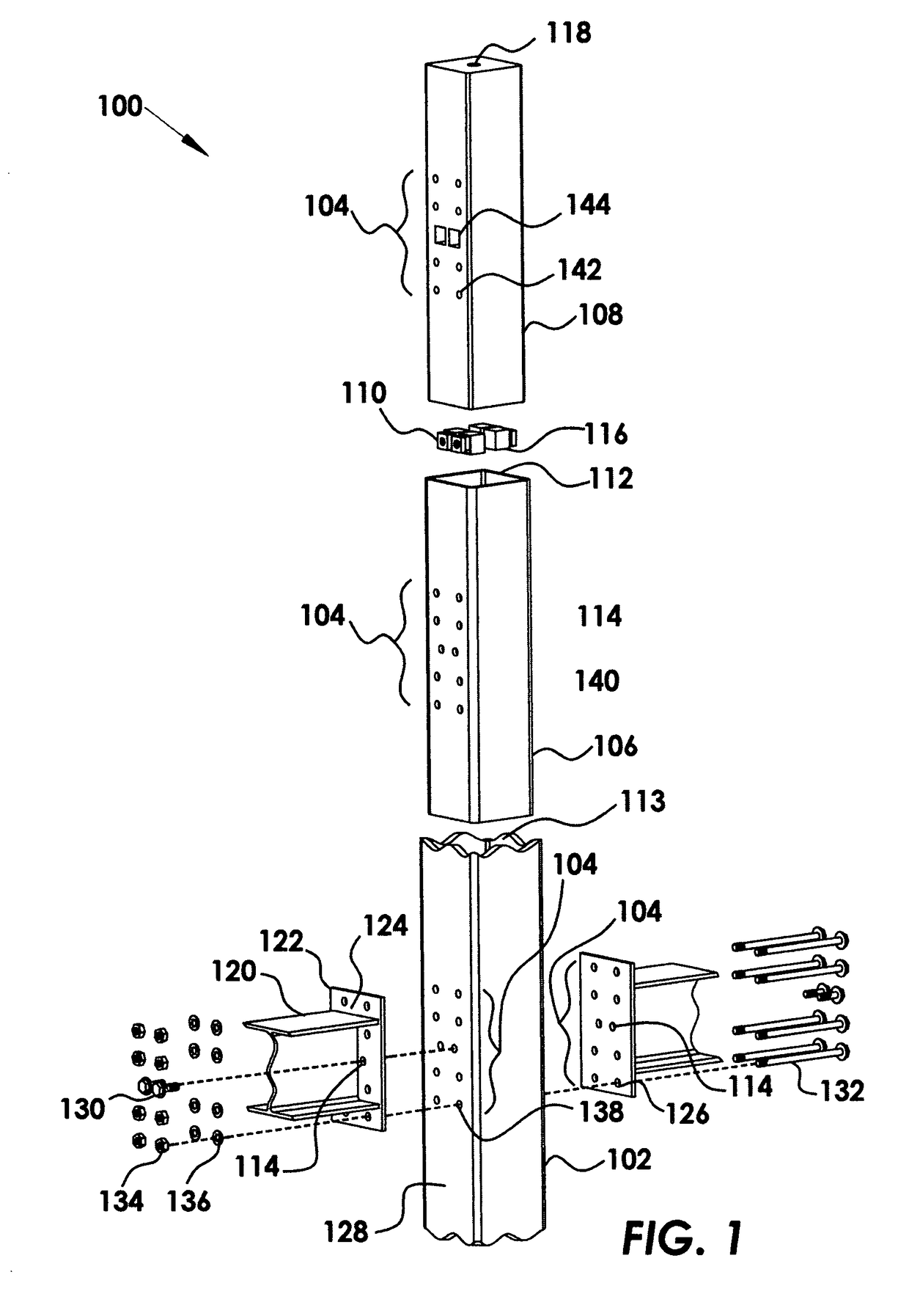
[0039]The present invention makes possible the erection of beams to columns, and the installation and pretension of the connection bolts possible in a single stop to each beam-column joint in the field. The current invention shortens the process of installing the connection bolts and, prior to pretensioning the connection bolts, filling the entire column with grout or concrete and waiting for the filler to harden to sufficient strength to resist the pretensioning of the connection bolts, then pretensioning the bolts. This would require mu...


PUM


Abstract

A moment resistant building column insert system is provided that enables the erection of beams to columns, and the installation and pretension of connection bolts possible in a single stop to each beam-column joint in the field. Included is a building column insert with pre-hardened structural filler inside, and a pattern of through-holes transverse to the insert length, where the insert has threaded elements disposed inside and concentric to erection holes in the pattern. The insert is disposed inside a building column. Erection bolts installed to the erection holes to hold the beam in place against the column with the holes in the beam mounting plate, the column and insert aligned. Connection through-bolts are installed and pretensioned to provide the connection strength needed to make a beam-column moment joint rigid. Without the pre-hardened structural filler in the insert the column would deform or crush due to the bolt pretensioning.

Description

CROSS-REFERENCE TO RELATED APPLICATIONS[0001]This application is a continuation-in-part application of U.S. patent application Ser. No. 11 / 373,719 filed Mar. 10, 2006 now U.S. Pat. No. 7,637,076. This application is cross-referenced to and claims the benefit from U.S. patent application Ser. No. 11 / 373,719 filed Mar. 10, 2006, which is hereby incorporated by reference.FIELD OF THE INVENTION[0002]The invention relates generally to building structures. More particularly, the invention relates to a building column insert that provides a moment-resistant alignment and connection between columns and beams, and column splices.BACKGROUND[0003]It is currently desirable to use moment-resistant structures in construction of new buildings because they offer fewer restrictions for design and more useful space, while adhering to building design codes. The moment-resistant structures must meet building code standards that require the moment-resistant connections to deflect and absorb energy resul...

Claims


Application Information

Patent Timeline
Patent Type & Authority Patents(United States)
IPC IPC(8): E04C3/00F16L41/00E04B1/38E04C5/00E04B1/00F16B9/00
CPCE02D27/34E04B1/24E04C3/06E04C3/32E04C3/30E04B2001/2415E04B2001/2418E04B2001/2445E04B2001/2454Y10T403/3986E04C2003/0452E04C2003/0465E04B2001/2463F16B9/01F16B9/02
Inventor VAUGHN, WILLAIM B.
Owner VAUGHN WILLAIM B
Why Eureka
Try Eureka