
Methods and arrangements for redirecting thrust from a propeller

a propeller and thrust technology, applied in the direction of marine propulsion, special-purpose vessels, vessel construction, etc., can solve the problems of difficult reverse maneuverability of inboards, inconvenient and idle speed in both forward and reverse is typically too fast for docking and removal of slack

Inactive Publication Date: 2013-06-25
HOBERMAN KEVIN DANIEL +1
View PDF15 Cites 30 Cited by
  • Summary
  • Abstract
  • Description
  • Claims
  • Application Information

AI Technical Summary

Benefits of technology

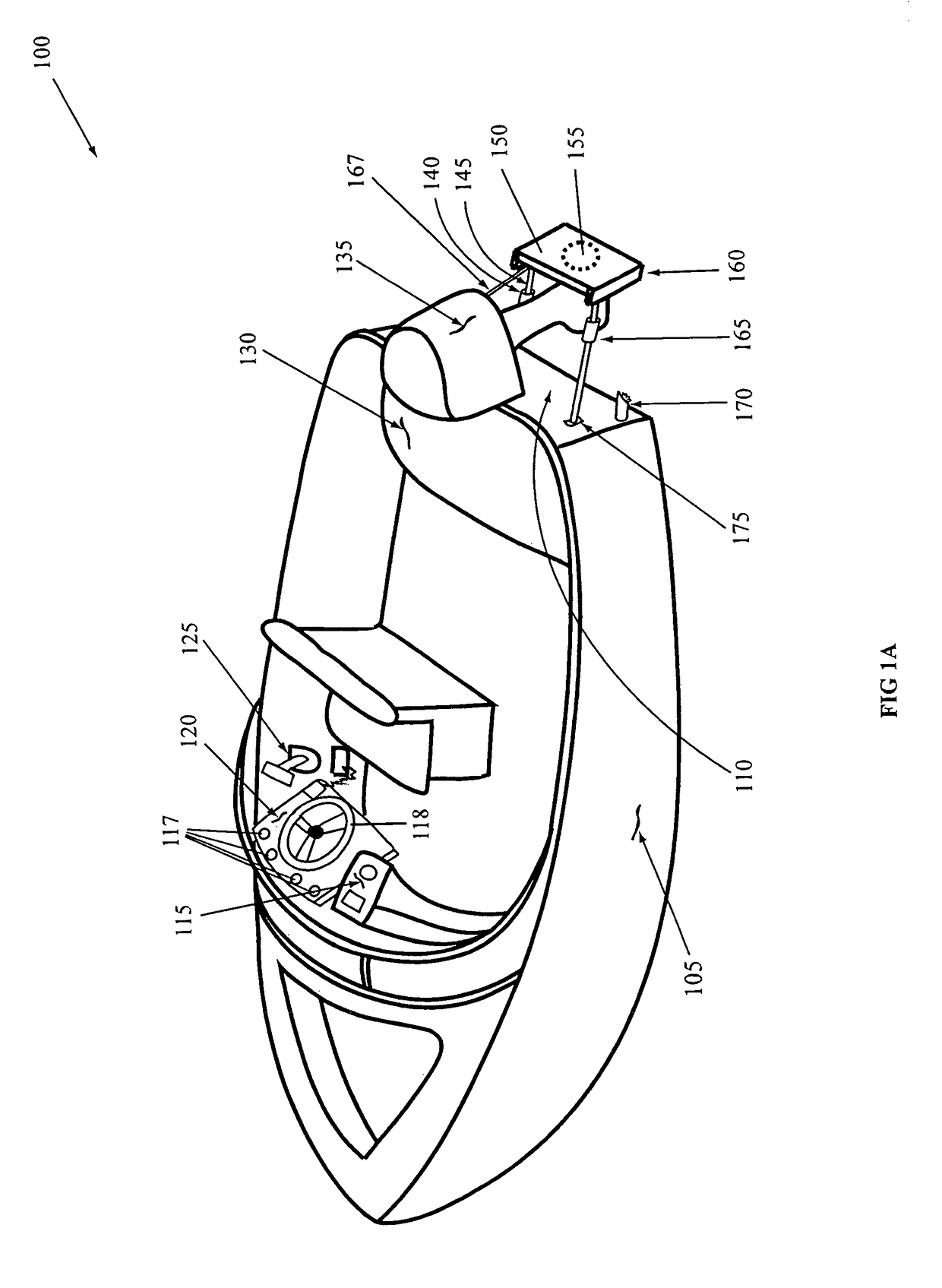
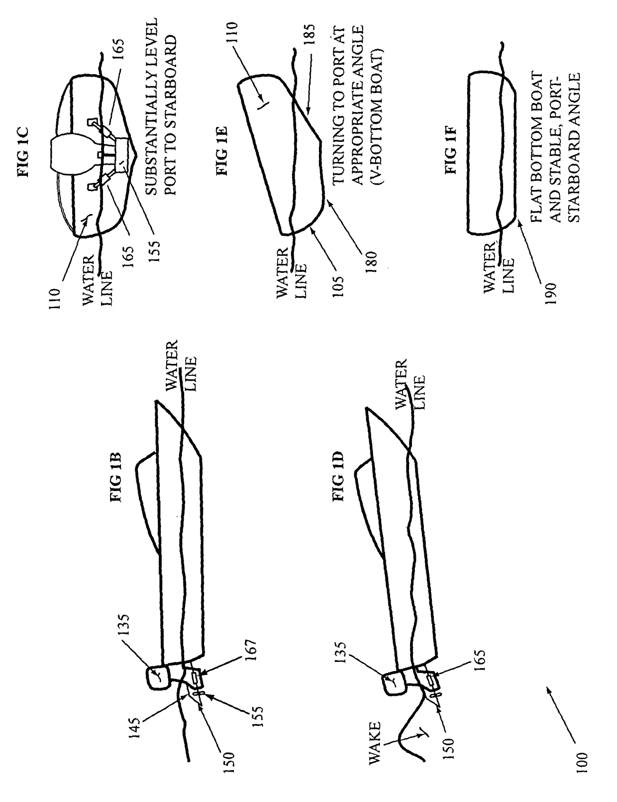
The patent describes methods and arrangements to redirect the thrust generated by a propeller of a watercraft to provide a reverse and / or sideways thrust. This is achieved by a control surface that is positioned in water within an area in which the propeller wash is expelled. The control surface applies force to adjust its position and the spatial relationship between it and the propeller. The redirected thrust, which is a component of non-forward thrust, helps to improve the watercraft's performance and maneuverability. The patent also includes a retrofit kit for existing watercraft, a controller, and a database to facilitate the implementation of the methods.

Problems solved by technology

In reverse, the rudder is not in the prop wash and, as a result, the inboards are difficult to maneuver in reverse, which is especially troublesome when attempting to maneuver the watercraft to a dock, onto a trailer or when preparing to pull a water skier.
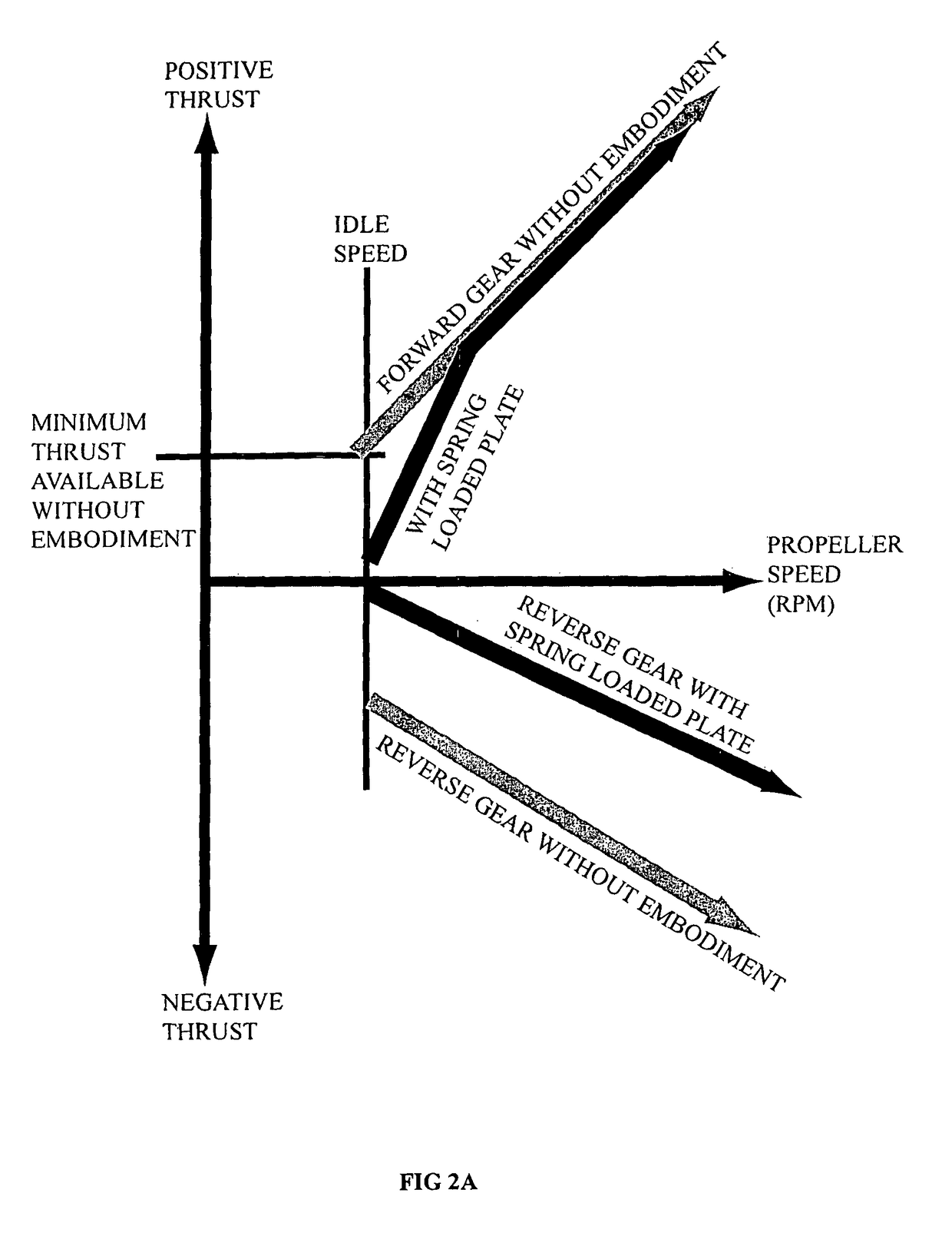
Because outboard drives typically have only one reverse, and one forward gear, the gear may provide too much thrust even in idle to easily dock the boat, which forces the person docking the boat to repeatedly switch between in gear and neutral to achieve slower speeds than possible at idle.
Also, when maneuvering to remove slack in a ski rope, idle speed is typically too fast.
Yet, idle speed in both forward and reverse is typically too fast for docking and for removing slack in a ski rope.

Method used


Image

  • Methods and arrangements for redirecting thrust from a propeller
  • Methods and arrangements for redirecting thrust from a propeller
  • Methods and arrangements for redirecting thrust from a propeller

Examples


Embodiment Construction

[0033]The following is a detailed description of example embodiments of the invention depicted in the accompanying drawings. The example embodiments are in such detail as to clearly communicate the invention. However, the amount of detail offered is not intended to limit the anticipated variations of embodiments, but on the contrary, the intention is to cover all modifications, equivalents, and alternatives falling within the spirit and scope of the present invention as defined by the appended claims. The detailed descriptions below are designed to make many such embodiments obvious to a person of ordinary skill in the art.

Introduction

[0034]Generally speaking, methods and arrangements to redirect a thrust generated by a propeller of a watercraft to provide a non-forward thrust are disclosed. More specifically, embodiments comprise a control surface such as a plate to redirect the thrust in response to generation of the thrust by the propeller. Based upon a position (i.e., distance a...


PUM


Abstract

Methods and arrangements to redirect a forward thrust generated by a propeller of a watercraft to provide a non-forward thrust are disclosed. More specifically, embodiments comprise a control surface to redirect the forward thrust from the propeller. Based upon a position (i.e., distance and orientation) of the control surface with respect to the propeller, the redirection generates the non-forward thrust or thrusts. By redirecting a component of the forward thrust back toward the bow, the net forward or reverse, port or starboard thrusts and rotational thrust can be adjusted in fine increments. For instance, by adjusting the amount of prop wash hitting the control surface, the magnitude of the redirected thrust from the control surface can be adjusted. Further, adjusting the angle of the control surfaces adjusts the direction as well as magnitude of a reverse thrust component. The net thrust can be in any direction and rotational.

Description

CROSS-REFERENCES TO RELATED APPLICATIONS[0001]Pursuant to 35 USC §119(e), this application claims priority to and benefit of U.S. Provisional Patent Application Ser. No. 60 / 609,717, filed Sep. 14, 2004.FIELD OF INVENTION[0002]The present invention is in the field of thrust control for propeller driven watercraft such as a boat. More particularly, the present invention relates to methods and arrangements to redirect a thrust generated by a propeller via a control surface for a watercraft to provide a non-forward thrust. Many such embodiments may advantageously provide finer and / or quicker adjustments to the net thrust, steering, wake control, tilt control and / or other control via the redirected thrust.BACKGROUND[0003]The watercraft designs differ the size, shape, and propulsion of the watercrafts. For instance, contemporary watercraft designs implement sails, jet engines, fans, water-jet propulsion drives, paddle drives, and motor-driven propellers for propulsion. Each type of propul...

Claims


Application Information

Patent Timeline
Patent Type & Authority Patents(United States)
IPC IPC(8): B63H5/125B63H20/00B63H25/00B63H5/16B63H25/44B63H25/48
CPCB63H25/44B63H25/48
Inventor HOBERMAN, KEVIN DANIELMOORE, STEVEN CLAY
Owner HOBERMAN KEVIN DANIEL
Learn More