Gripping device of working machine and working machine with the same

a technology of working machine and gripping device, which is applied in the direction of gripping head, load-engaging elements, constructions, etc., can solve the problems of preventing a sufficient driving force from being transmitted to the grip object, and affecting the gripping force of the working machine. fine adjustment

Inactive Publication Date: 2013-06-25
KOBELCO CONSTR MASCH CO LTD
View PDF17 Cites 2 Cited by
  • Summary
  • Abstract
  • Description
  • Claims
  • Application Information

AI Technical Summary

Benefits of technology

[0012]In the gripping device, when the gripping driving cylinder is extended and contracted, by the spring member provided between the gripping driving cylinder and the gripping member body included in at least one of the first gripping member and the second gripping member, the gripping member bodies rotate in the closing directions while the gripping member bodies and the connecting shaft are held in the predetermined positional relationship. The gripping member bodies come into contact with a processing object, and retreat with respect to the connecting shaft while the spring member is elastically deformed by an opposing force received from the processing object. In a range in which the gripping member bodies retreat, regardless of the driving force of the gripping driving cylinder, contact pressure of the gripping member bodies with respect to the processing object becomes pressure corresponding to the elastic force of the spring member. Therefore, it is possible to perform fine adjustments of the contact pressure. When the retreating of the gripping member bodies exceeds the predetermined range, the driving force of the gripping driving cylinder acts upon the processing object as it is, thereby making it possible to grip the processing object by a large gripping force.
[0013]In the present invention, when the predetermined range is exceeded, the driving force acts directly upon the gripping member bodies from the connecting shaft. Therefore, the gripping member bodies can retreat without interposing another member between the connecting shaft and the gripping member bodies that grip the processing object. Consequently, for example, compared to a structure in which, in order to allow a gripping member body to retreat, the gripping member body is divided into two portions, and the two portions are connected to each other so that the two portions are displaced relative to each other, the structure for gripping and breaking the processing object (the gripping member bodies in the present invention) can have sufficient strength. The spring member, which is interposed between the connecting shaft and the gripping member body, is provided for applying elastic force to the connecting shaft in the retreating range (the predetermined range). In the rotation range of the gripping member bodies exceeding the predetermined range, the connecting shaft and the gripping member bodies contact each other, and driving force is directly transmitted to the gripping member bodies from the connecting shaft.
[0014]More specifically, the gripping member body has a through groove capable of receiving the connecting shaft and having a shape allowing the gripping member body to retreat with respect to the connecting shaft. Here, by bringing an inner surface at the through groove and the connecting shaft into contact with each other in a closing direction of the gripping members among the extension direction and the contraction direction of the gripping driving cylinder, the gripping member body is prevented from retreating by an amount exceeding the predetermined amount.
[0016]According to this structure, since the elastic force of the spring member can be widely used within the restricted retreating range of the gripping member bodies, it is possible to more finely adjust the gripping force.
[0020]According to this structure, since each spring member can be disposed at a position that is separated from an end of the other gripping member and the gripping member body that grips a processing object, the probability with which the spring member contacts the processing object is low, thereby making it possible to restrict breakage of the spring member.

Problems solved by technology

However, a large gripping device, such as that mentioned above, used for the purpose of performing, for example, a powerful breaking operation can seldom grip a relatively small work object without breaking the small work object.
In such a powerful gripping device, the gripping force varies greatly even by a slight operation performed by an operator, thereby making it difficult for the operator to finely adjust the gripping force by operating the powerful gripping device.
However, since the grip object is gripped by the link connecting members that can be bent along the periphery of such a gripping device, even if the arm cylinder that opens and closes the gripping links is one providing a large output, the link connecting members are deformed, thereby preventing a sufficient driving force from being transmitted to the grip object.
However, even if such auxiliary gripping members are mounted, the driving force of the cylinder device is transmitted to the processing object as it is, thereby making it difficult to perform fine adjustments of the gripping force.
In addition, there is a considerable limit as to how thick the elastic material can be made, as a result of which it is actually impossible to effectively accommodate a sudden increase in the gripping force by elastic deformation of the elastic material alone.

Method used


Image

  • Gripping device of working machine and working machine with the same
  • Gripping device of working machine and working machine with the same
  • Gripping device of working machine and working machine with the same

Examples


Embodiment Construction

[0033]Preferred embodiments of the present invention will hereunder be described with reference to the drawings.

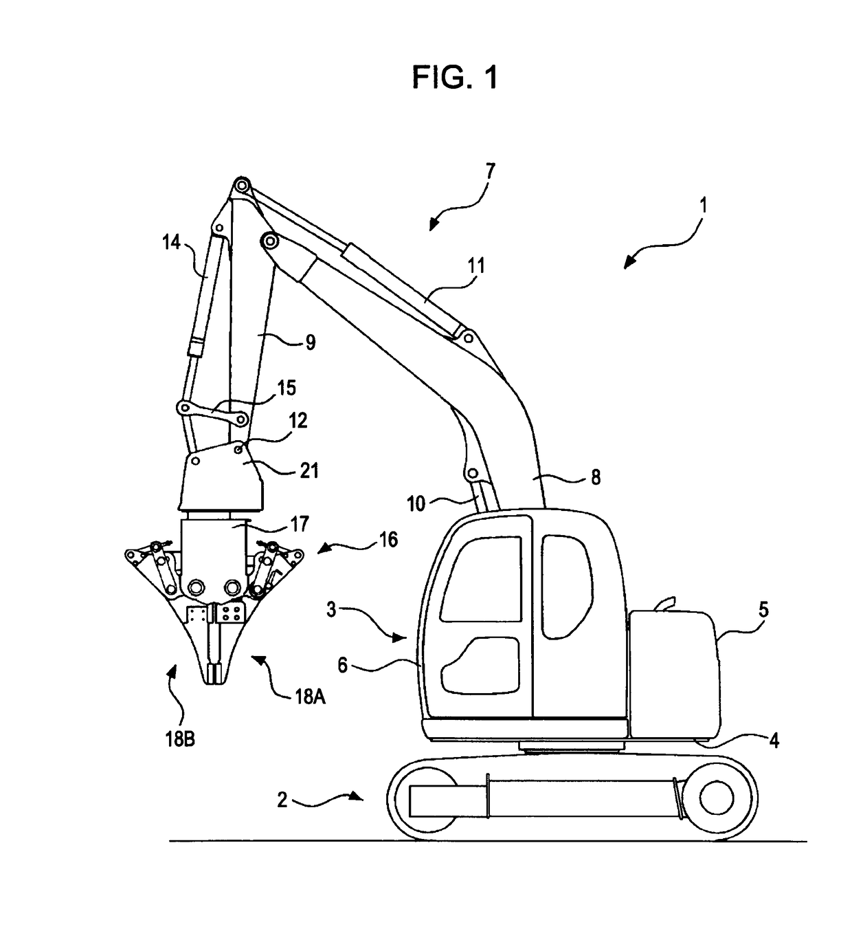
[0034]FIG. 1 shows a gripping device and a working machine including the gripping device according to an embodiment of the present invention. Although, in FIG. 1, a hydraulic excavator is used as a working machine, the working machine according to the present invention is not limited thereto. The present invention is applicable to various other working machines including a working arm whose end is displaceable.

[0035]A hydraulic excavator 1 includes a lower traveling structure 2 and an upper rotating structure 3 rotatably mounted on the lower traveling structure. The upper rotating structure 3 includes a rotating frame 4, with a counterweight 5, a cabin 6, and a working arm 7 being mounted on the rotating frame 4.

[0036]The working arm 7 includes a boom 8 and an arm 9, and a boom cylinder 10 and an arm cylinder 11 for driving the boom 8 and the arm 9, respectively. The boom ...


PUM


Abstract

A gripping device includes a spring member provided between a gripping member body and a shaft so that driving of a gripping driving cylinder causes a driving force to be transmitted from the gripping driving cylinder to the body while the shaft and the body are held in a predetermined positional relationship; so that the body is allowed to retreat with respect to the shaft by elastically deforming the spring member by an opposing force received from a processing object that contacts the body as a result of rotating the body; and so that contact pressure of the body with respect to the processing object is increased by an elastic force of the spring member as the body retreats.

Description

BACKGROUND OF THE INVENTION[0001]1. Field of the Invention[0002]The present invention relates to a gripping device provided at an end of a working arm of a working machine such as a hydraulic excavator, and used for gripping a processing object for, for example, tearing down a building or breaking up and separating industrial waste; and to a working machine including the gripping device.[0003]2. Description of the Related Art[0004]Hitherto, a gripping device discussed in Japanese Patent No. 2691795 (hereunder referred to as “Patent Document 1”) is known as a gripping device provided at an end of a working arm of a working machine. The gripping device includes a frame bracket, a pair of arm links, an arm cylinder, and link connecting members for gripping. The frame bracket is mounted to the end of the working arm. The pair of arm links are provided at the frame bracket so as to be openable and closable with respect to the frame bracket. The arm cylinder opens and closes the arm links...

Claims


Application Information

Patent Timeline
Patent Type & Authority Patents(United States)
IPC IPC(8): B66C1/22B66C1/36B66C3/16
CPCB66C1/427E02F3/965E02F3/4135
Inventor MURAOKA, DAISUKEMUKAI, MICHIHARUYAMASAKI, TAKANORI
Owner KOBELCO CONSTR MASCH CO LTD
Why Eureka
Try Eureka