
Variable gain mouse

a mouse and variable gain technology, applied in the field of variable gain mouse, can solve the problems of one may decrease the gain, and achieve the effects of reducing the gain, rapid motion, and relatively high gain

Active Publication Date: 2013-06-25
STMICROELECTRONICS SRL
View PDF14 Cites 0 Cited by
  • Summary
  • Abstract
  • Description
  • Claims
  • Application Information

AI Technical Summary

Benefits of technology

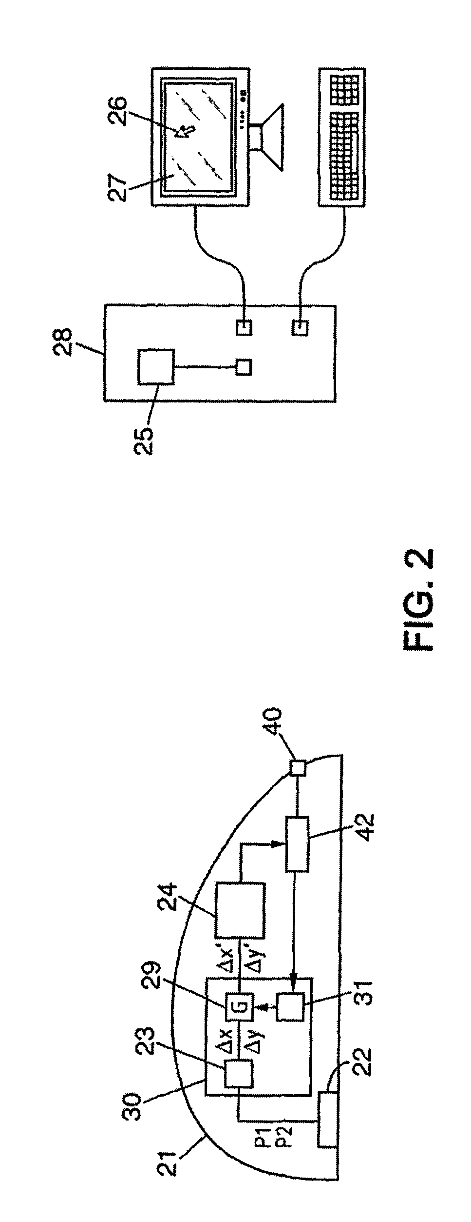
[0033]In this manner one may decrease the gain when the capture device, for example a mouse, captures a relatively rapid motion. This avoids the problems related to overflow during transmission to the host device.
[0034]When the capture device captures a relatively slow motion, the gain may be relatively high. The captured motion, represented for example by the apparent displacement of a pointer on a screen of the host device, is thus relatively high. For a screen comprising a relatively high number of pixels, this avoids a decrease in the apparent displacement of the pointer on the screen for a given displacement of the mouse. In addition, the precision remains relatively high. The loss of precision due to a quantification of the motion as a number of counts is relatively low. And the factor applied by the host device may be relatively low, avoiding minimum displacements on the screen that exceed one pixel. In other words, each pixel on the screen may be reached by the pointer.
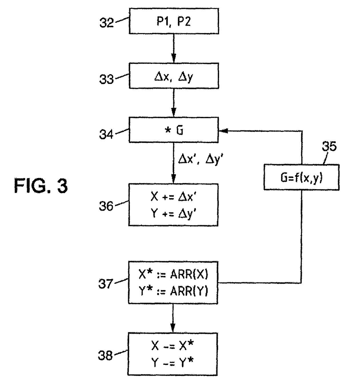
[0037]Advantageously, the adjusting means are arranged to modify the gain as a function of the sum of multiple previously acquired displacement measurements. This corresponds to low-pass filtering (or smoothing), which avoids variations in the gain due to excessive sensitivity.
[0040]Conventional mouse capture devices commonly integrate the accumulator and such a means of communication. For example, one may obtain mice according to the first embodiment of the invention relatively easily, for example by modifying a computer program executed by a mouse processor.

Problems solved by technology

In this manner one may decrease the gain when the capture device, for example a mouse, captures a relatively rapid motion.

Method used


Image

  • Variable gain mouse
  • Variable gain mouse
  • Variable gain mouse

Examples


Embodiment Construction

[0065]The capture system represented in FIG. 2 comprises a capture device and a host device, which in this embodiment are respectively an optical mouse 21 and a central processing unit 28 of a computer.

[0066]The mouse 21 comprises an optical sensor and a lens, labeled as number 22. The sensor captures image data P1, P2 and sends these image data to displacement determination means 23. The image data P1, P2 typically correspond to images captured at given instants. The determination means receive the image data (step 32 in FIG. 3). By comparing the image data P1, P2 captured between two instants, the determination means 23 determines a displacement measurement (Δx,Δy) in two dimensions x, y, corresponding to an interval of time between these two instants (step 33 in FIG. 3).

[0067]Each displacement measurement (Δx,Δy) is counted as counts, with each count corresponding to a 32nd of a point.

[0068]For example, for a sensor associating a point with a distance of 30 μm, and for a lens wit...


PUM


Abstract

A motion capture device for communicating with a host device in order to input captured motion. The device includes an amplifier module structured to weight displacement measurements by a gain, and an adjustment module structured to adjust the gain as a function of a speed of the capture device.

Description

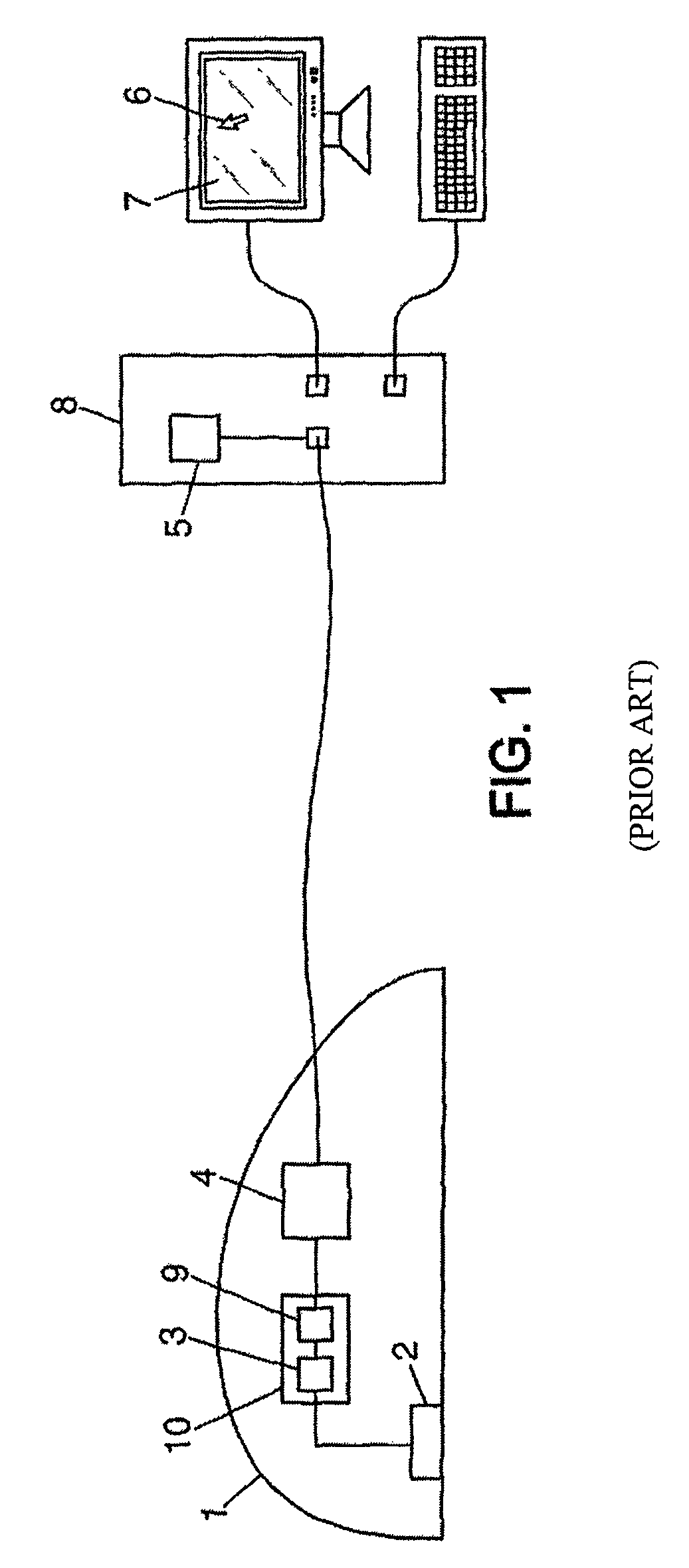
BACKGROUND[0001]1. Technical Field[0002]The present invention relates to motion capture devices cooperating with a host device in order to record captured motion, particularly, but not limited to, mice intended to communicate with a computer.[0003]2. Description of the Related Art[0004]FIG. 1 shows an example of a known motion capture and display system. A device 1, for example an optical mouse, comprises measuring means 2, 3 comprising for example a lens and a sensor represented by 2. The sensor captures images, which it sends to displacement determination means 3. These means 3 compare the images received to determine a displacement between successive images.[0005]Such displacement is commonly measured in two dimensions. In the present description, the terms “displacement”, “points”, “counts”, “displacement measurement”, “number of pixels”, etc. are commonly understood to mean pairs of values, for example (X, Y). Of course, the concepts of “displacement”, “points”, etc. may also c...

Claims


Application Information

Patent Timeline
Patent Type & Authority Patents(United States)
IPC IPC(8): G09G5/00G06F3/033G06F3/0354G06F3/038
CPCG06F3/03543G06F3/0383
Inventor MELLOT, PASCALGLAIS, ARNAUD
Owner STMICROELECTRONICS SRL
Learn More